
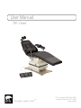
User Manual
U.S. & Canada (888) 520-4998
International (801) 875-4998
www.mti.net
721 Chair
Strength in patient care.™

THIS PAGE IS INTENTIONALLY BLANK.

Table of Contents iii
APPLICABLE MODEL(S) ..................................................................................................................................................................................................................................................................................... IV
REVISION HISTORY TABLE ........................................................................................................................................................................................................................................................................... IV
GENERAL INFORMATION .....................................................................................................................................................................................................................................................................................
Purpose of this Manual .........................................................................................................................................................................................................................................................................1
Intended Use ......................................................................................................................................................................................................................................................................................................... 1
Symbols and Warnings..........................................................................................................................................................................................................................................................................2
Symboles et Avertissements .........................................................................................................................................................................................................................................................2
Safety Instructions .......................................................................................................................................................................................................................................................................................3
Electromagnetic Interference ......................................................................................................................................................................................................................................................4
Electrical Requirements ...................................................................................................................................................................................................................................................................... 4
Contraindications ...........................................................................................................................................................................................................................................................................................5
Transportation and Storage Conditions ........................................................................................................................................................................................................................5
Disposal of Equipment ..........................................................................................................................................................................................................................................................................5
EQUIPMENT FEATURES .......................................................................................................................................................................................................................................................................................
INSTALLATION .....................................................................................................................................................................................................................................................................................................................
Required Tools .................................................................................................................................................................................................................................................................................................... 7
Explanation of Instructions .............................................................................................................................................................................................................................................................7
Unpacking and Set-up ........................................................................................................................................................................................................................................................................ 8
OPERATION ............................................................................................................................................................................................................................................................................................................................
Operating Conditions ..............................................................................................................................................................................................................................................................................9
Controls ....................................................................................................................................................................................................................................................................................................................10
Headrest Operation ...................................................................................................................................................................................................................................................................................11
Electrical Lockout .......................................................................................................................................................................................................................................................................................12
Mobile Base Operation ...................................................................................................................................................................................................................................................................... 12
Swivel Base Operation ........................................................................................................................................................................................................................................................................ 13
LIST OF ACCESSORIES ......................................................................................................................................................................................................................................................................................
MAINTENANCE ..................................................................................................................................................................................................................................................................................................................
Cleaning and Disinfection .............................................................................................................................................................................................................................................................. 18
Preventative Maintenance ..............................................................................................................................................................................................................................................................18
Fuse Replacement Instructions ...........................................................................................................................................................................................................................................18
Scu Cover Replacement Instructions ......................................................................................................................................................................................................................19
Calls for Service ............................................................................................................................................................................................................................................................................................19
LIMITED WARRANTY ..............................................................................................................................................................................................................................................................................................
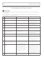
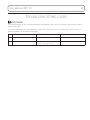
TROUBLESHOOTING GUIDE .....................................................................................................................................................................................................................................................................
SPECIFICATIONS ..........................................................................................................................................................................................................................................................................................................

iv User Manual | MTI 721
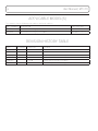
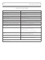
APPLICABLE MODEL(S)
This manual is for the following part numbers and serial numbers:
PART NUMBER DESCRIPTON EFFECTIVE S/N
7000044 721 Contour Seat Surgery Chair, 115V 090412004 - Current
7000045 721 Contour Seat Surgery Chair, 230V 090412004 - Current
REVISION HISTORY TABLE
DATE REVISION CO#/ECO# DETAILS
-ORG Initial Release
4/29/2009 042909
11/09/2010 A
6/6/2017 B CO-0068 Update Manual to new manual format
11/06/2017 C CO-0143 Update Safety Lockout Procedures
12/6/2019 D CO-0187 Revised Proposition 65 warning

GENERAL INFORMATION
Purpose of this Manual
This manual covers the safety, installation, instructions for use, and maintenance
of this equipment. It is intended that it be used by the service professional
installing the equipment and by the medical professionals who have been trained
to use it. No repair information is included with this manual because no operator
repairs are intended.
Intended Use
This equipment is intended to be used as a chair for general examinations and
procedures performed by medical professionals.
PRODUCT INFORMATION
Date of Purchase:
Model Number:
Serial Number:
(see “EQUIPMENT FEATURES” on page 6 for location of serial number label)
User Manual
MTI 721 Chair

2 User Manual | MTI 721
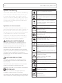
Symbols and Warnings
This manual contains Notices, Cautions, and Warnings,
which are meant to call attention to particular parts
or sections of this manual. Since safety is our first
concern, this manual should be read by all personnel
who will be operating this medical equipment. Failure
to comply with the following warnings and cautions
will void the warranty.
Symboles et Avertissements
Ce manuel contient des avis, des précautions et des
avertissements qui sont destinés à attirer l’attention sur
des pièces ou des sections de ce manuel particulier.
Parce que la sécurité est notre première préoccupation,
ce manuel doit être lu par tout le personnel qui
sera d’utiliser cet équipement médical. Défaut de se
conformer avec les avertissements et les précautions
de ce guide d’instruction annulera la garantie.
WARNINGS/AVERTISSEMENTS
Are used to call attention to a condition, practice, or
procedure which could cause personal injury if not
followed correctly. Please become familiar with all
warnings and observe them at all times.
Sont utilisés pour attirer l’attention sur une condition,
pratique ou procédure qui pourrait causer des blessures
s’il n’est pas suivi correctement. S’il vous plaît se
familiariser avec tous les avertissements et les observer
à tout moment.
CAUTIONS/PRECAUTIONS
Are used to call attention to a condition, practice, or
procedure which could cause product damage if not
used correctly.
Sont utilisés pour attirer l’attention sur une condition,
pratique ou procédure qui pourrait causer des
dommages au produit s’il n’est pas utilisé correctement.
NOTICES/AVIS
Are used to call attention to helpful information
regarding a condition, practice, or procedure.
Sont utilisés pour attirer l’attention sur des informations
utiles concernant une condition, pratique ou de procédure.
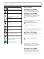
Class 1, Type B, Medical Equipment
Proper shipping orientation for the product
Orientation d’embarquement correct pour
le produit
Product is fragile; be careful in handling
Le produit est fragile. Soyez prudent lors
de la manipulation
Protective earth ground
Terre électrique de protection
Alternating current
Le courant alternatif
15 sec
5 min
Unit duty cycle of 10% Example: (1) minute
on (9) minutes o
Unité rapport cyclique du 10%
Product must be kept dry
Le produit doit rester sèche
Upper and lower limits of temperature
Limites haute et basse de la température
2
Maximum stacking height of palletized
units
Hauteur maximale de la pile d’unités sur
palettes.
Indicates the presence of a dangerous
voltage/shock hazard
Indique le présence de voltage
dangereux/ de choc
Follow instructions for use
Suivez les instructions pour l’utilisation
Consult operating instructions
Consultez les instructions d’utilisation
Manufacturer of product
Fabricant de produits
Date on which the product was
manufactured
Date de fabrication

User Manual | MTI 721 3
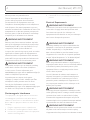
Identifies the manufacturer’s serial number
Identifie le numéro de série du fabricant
Upper and lower limits of relative humidity
Limites haute et basse de humidité relative.
Upper and lower limits of atmospheric
pressure
Limites haute et basse de la pression
atmosphérique
Location of fuses
Emplacement de fusibles
(WEEE) Waste of Electrical and Electronic
Equipment
Déchets d’équipements électriques et
électroniques
ETL listing mark
Marque ETL Listé
UL listing mark
Marque UL Listé
European Conformity mark
Marque Conformité Européenne
Connection point for the neutral conductor
Point de connexion pour le conducteur neutre
Live conductor
Conducteur sous tension
Hospital Grade (green dot)
De qualité hôpital (point vert)
Safety Instructions
WARNING/AVERTISSEMENT
Read this manual before installation and use.
Lisez ce manuel avant l’installation et l’utilisation.
WARNING/AVERTISSEMENT
No modification of this equipment is allowed.
Aucune modification de cet équipement est autorisé.
WARNING/AVERTISSEMENT
Do not operate equipment in the presence of
flammable anesthetics.
Ne pas faire fonctionner l’équipement en présence
d’anesthésiques inflammables.
WARNING/AVERTISSEMENT
When the equipment is in motion from a programmable
position or auto return, injury may occur if the
equipment is not attended to until it comes to a
complete stop.
Lorsque l’équipement est en mouvement à cause d’une
position programmable or retour automatique, blessure
peut se produire si l’équipement n’est pas regardé
jusqu’à ce qu’il arrive à un arrêt complet.
WARNING/AVERTISSEMENT
Verify equipment, patient, and other objects are in a safe
condition before operating the equipment.
Vérifiez l’équipement, patient, et d’autre objets sont dans
un état sûr avant d’utiliser l’équipement.
WARNING/AVERTISSEMENT
Verify controls, cords, and other parts of the equipment
do not create a tripping or other safety hazard for
operator or patient.
Vérifiez les contrôles, les cordons et les autres
parties de l’équipement ne créent pas un risque de
trébuchement ou d’autres risques d’accident pour
l’opérateur ou le patient.
WARNING/AVERTISSEMENT
Turn the lockout switch to the o position to
prevent unintentional chair movements caused by
electromagnetic interference or radio frequency
interference from other equipment or from accidental
activation of the chair controls. Failure to do so may
result in personal injury. Turning the lockout switch o

4 User Manual | MTI 721
will not prevent non-powered motion.
Tourner l’interrupteur de verrouillage sur la
position arrêt pour prévenir des mouvements
non intentionnels de l’équipement causés par
l’interférence électromagnétique ou des interférences
radio-fréquence d’un autre équipement ou par une
activation accidentelle des commandes de chaise. Tout
manquement à ces directives peuvent provoquer des
blessures graves. Le fait de désactiver le verrouillage
n’empêche pas le mouvement non alimenté.
WARNING/AVERTISSEMENT
Backrest, seat, footrest, armrest, headrest, and other
parts of the equipment should only be used for their
intended purpose. MTI is not responsible for use of
components outside of their intended use.
Le repose-dos, reste de siège, repose pieds, accoudoirs,
appuie-tête et d’autres parties de l’équipement ne
doivent être utilisés conformément à leur utilisation
prévue. MTI n’est pas responsable de l’utilisation des
composants au dehors de leur utilisation prévue.
WARNING/AVERTISSEMENT
This product can expose you to chemicals including
nickel, which is known to the State of California
to cause cancer. For more information go to
www.P65Warnings.ca.gov and see www.mti.net/faqs for
details on California Proposition 65.
Ce produit peut vous exposer à des agents
chimiques, y compris le nickel, identifiés par l’État
de Californie comme pouvant causer le cancer.
Pour de plus d’informations, prière de consulter
www.P65Warnings.ca.gov et voir www.mti.net/faqs pour
les détails sur le Proposition de Californie 65.
Electromagnetic Interference
This equipment is designed and built to minimize
electromagnetic interference with other devices.
However, if interference is noticed between another
device and this equipment, do one or more of the
following:
1. Plug the equipment into an isolated circuit.
2. Remove the interfering device from the room.
3. Increase the separation between the equipment
and the interfering device.
4. Contact MTI if the electromagnetic interference
persists.
Electrical Requirements
WARNING/AVERTISSEMENT
To avoid risk of electrical shock, this equipment must be
connected to a supply mains with protective earth.
Pour éviter tout risque de choc électrique, cet
équipement doit être branché sur une prise électrique
avec la terre électrique de protection.
WARNING/AVERTISSEMENT
Grounding reliability can only be achieved when the
equipment is connected to an equivalent receptacle
marked “Hospital Only” or “Hospital Grade”.
Mise à la terre fiabilité ne peut être atteint lorsque
l’équipement est connecté à un réceptacle équivalent
marqué “Hôpital Uniquement“ ou “de Qualité Hôpital”.
WARNING/AVERTISSEMENT
When using endocardial catheters or high frequency
surgical/procedure devices, use non-conductive material
to insulate the patient from metal portions of the
equipment. Failure to comply may result in electric
shock or burns to patient.
Lors de l’utilisation de cathéters endocavitaires ou
dispositifs chirurgicale / procédure haute fréquence,
utiliser un matériau non conducteur pour isoler le
patient des parties métalliques de l’équipement. Le
non-respect peut entraîner un choc électrique ou de
brûlures pour le patient.
WARNING/AVERTISSEMENT
Connecting electrical equipment to a multiple socket-
outlet eectively leads to creating a medical electronic
system and can result in a reduced level of safety.
Connexion d’un équipement électrique à une prise de
courant multiple crée un système électronique médicale,
et peut entraîner une baisse du niveau de sécurité.
WARNING/AVERTISSEMENT
Equipment must be positioned in normal use such that
the power cords can be easily accessed to unplug.
L’équipement doit être positionné en utilisation normale

User Manual | MTI 721 5
telle que les cordons d’alimentation peuvent être
facilement accessibles à débrancher.
WARNING/AVERTISSEMENT
Equipment must be connected to an appropriate power
source when loss of power source would result in an
unacceptable risk.
L’équipement doit être relié à une source d’alimentation
appropriée en cas de perte de la source d’alimentation
entraînerait un risque inacceptable.
WARNING/AVERTISSEMENT
Do not use a two-three plug adapter to plug the
equipment into a two conductor outlet, as grounding
reliability is not maintained.
Ne pas utiliser un adaptateur non de prise de terre
pour brancher l’équipement sur une prise à deux
conducteurs, la fiabilité de la terre n’est pas maintenue.
WARNING/AVERTISSEMENT
Do not plug this equipment into a low power or
auxiliary outlet. This equipment must be connected to
a 115 Volt (V) outlet. If this equipment is connected to
an insucient power source, it will cause irreparable
damage to this device’s electronics.
Ne branchez pas cet équipement sur une prise de
faible puissance ou une prise auxiliaire. Cet équipement
doit être branché sur une prise de 115 Volt (V) . Si cet
équipement est connecté à une source d’alimentation
insusante, il causera des dommages irréparables à
l’électronique de cet appareil.
CAUTION/PRÉCAUTION
An appropriately rated surge protector must be used to
protect the printed circuit board. Warranty is void if this
surge protector is not used.
Un protecteur de surtension correctement classé doit
être utilisé pour protéger la carte de circuit imprimé. La
garantie est nulle si, ce protecteur de surtension n’est
pas utilisé.
NOTICE/AVIS
Removing the power supply cord at the equipment
input or wall receptacle will simultaneously isolate both
poles of the power supply.
Retrait du cordon d’alimentation à l’équipement ou
à la prise murale se isoler simultanément les deux
pôles de l’alimentation.
Contraindications
None.
Transportation and Storage Conditions
Ambient
Temperature
+10°C to +40°C
(+50°F to +104°F)
Relative
Humidity
30% to 75%
(non-condensing)
Atmospheric
Pressure
700hPa to 1060hPa
(0.69atm to 1.05atm)
Disposal of Equipment
At the end of product life, the equipment, accessories,
and other consumable goods may have become
contaminated due to normal medical use. Consult
local codes and ordinances for proper disposal of
equipment, accessories and other consumable goods.

6 User Manual | MTI 721
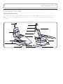
EQUIPMENT FEATURES
Description of 721 Chair/Table
A Tri-Power Exam Chair including power lift, back, and tilt with a 650 lb (295 kg) lift capacity. The 721 chair is 21"
(53.3 cm) wide with a 19" (48.3 cm) minimum height. The chairs are used for positioning a patient for exams and
procedures.
CHAIR
Electrical Lockout
Switch
Scu Cover
Headrest
Backrest
Seat/Footrest
Headrest Angle
Adjustment Knob
Headrest Height
Adjustment Knob
Foot/Hand Control Connector
Power Cord
Leveling Glides
Floating Arm Spline Mount
(Optional)
Headrest Angle
Adjustment Handle
Body Strap Snaps
Patient Arm Sling Snaps
Serial Number Label (under covers)

User Manual | MTI 721 7
Required Tools
7/16" Wrench
5/8" Wrench
Wire cutters Utility Knife Flat Head
Screwdriver
Phillips
Screwdriver (#2)
5/64" Allen
Wrench
Swivel Base Only:
9/16” Wrench
Explanation of Instructions
Instructions have steps which are designated by a number. Each step may also have sub-steps designated by a letter.
For example, an instruction to operate a feature may have 4 steps (1-4) and each of those steps may have sub-steps
(A-B) to be performed before moving on to the next step.
INSTALLATION
WARNING/AVERTISSEMENT
This equipment is heavy. Get help to remove it from
the shipping pallet. Use proper lifting procedures when
lifting to avoid serious back injury.
Cet équipement est lourd. Obtenir de l’aide pour le
retirer de la palette d’expédition. Utilisez les procédures
propre de levage pour le soulever pour éviter grave
blessure au dos.
WARNING/AVERTISSEMENT
After equipment is installed, verify that the
programmable positions are in safe and known positions.
Après l’équipement est installé, vérifier que les positions
programmables sont dans des positions sûres et connues.
CAUTION/PRÉCAUTION
To move equipment, lift only from the equipment’s main
structure.
Pour déplacer l’équipement, soulevez seulement de la
structure principale de l’équipement.
NOTICE/AVIS
If this product has been exposed to low temperatures,
allow adequate time for it to warm to room temperature
before putting it into service.
Si ce produit a été exposé à de basses températures,
laisser susamment de temps pour lui permettre de se
réchauer à température ambiante avant de le mettre
en service.
NOTICE/AVIS
Inspect the shipping boxes for visible damage. Record
on bill of lading, photograph, and report any damage
to the carrier immediately. Request an inspection by the
carrier if any concealed damage is noted.
Inspectez les boîtes d’expédition pour les dommages
visibles. Fiche sur le connaissement, prendre une
photo, et signalez les dommages dûs au transporteur
immédiatement. Demander une inspection par le
transporteur en cas de dommage caché est noté.

8 User Manual | MTI 721
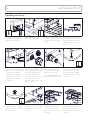
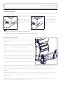
Unpacking and Set-up
1. Remove shipping straps,
shipping box, and other
boxes from the pallet.
2. Remove (4) shipping bolts
with 7/16" end wrench.
3. Remove braces from the
top of the baseplate. Braces
will vary for swivel/mobile
bases.
4. Slide chair o pallet. To
move equipment, lift only
from the equipment’s main
structure. Recycle or re-use
pallet.
Yellow
5. Insert power cord at the
base of the chair and secure
with the clip. Plug the power
cord into the provided
surge protector. Plug the
surge protector into an
appropriately marked
receptacle.
6. Install control(s) by
aligning pins and tabs of the
male control plug with chair
receptacle by positioning
the yellow mark on the
plug body to the 12 o’clock
position relative to the
receptacle at the lower rear
of the chair base.
7. Secure the plug by
rotating the locking ring
clockwise until it engages.
Rotate it until it stops.
Steps 8 through 9 do not
apply to mobile base chairs.
8. If chair base plate needs
to be leveled, remove (4)
acorn nuts from the top
of the glides with a 5/8"
wrench, otherwise proceed
to step 10.
9. Adjust individual glides to
level the chair as needed
using a screwdriver. Reattach
the acorn nuts.
10. Attach the flap to the
top of the seat section and
to the bottom of the back
section.
11. Align the seat cushion
with the seat section of
the chair and press into
place. Verify the cushion is
centered.
12. Align the back cushion
with the back section of
the chair and press into
place. Verify the cushion is
centered.

User Manual | MTI 721 9
Back of chair
14. Wrap the decorative base
strap around the plastic base
cover and attach Velcro®.
15. Swivel base chairs only.
Remove swivel bolt with
9/16” wrench.
Keep the bolt for use while
the chair is not powered.
OPERATION
Operating Conditions
Ambient Temperature +10°C to +40°C (+50°F to +104°F)
Relative Humidity 30% to 75% (non-condensing)
Atmospheric Pressure 700hPa to 1060hPa (0.69atm to 1.05atm)

10 User Manual | MTI 721
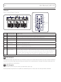
Controls
Foot Control/Hand Control
1 2 3
54 67 8
12
3non
functional
4
5
6
7
8
ITEM DESCRIPTION FUNCTION
1 Lift Pedal/Button Raises or lowers the chair top by pressing the desired direction
2 Back Pedal/Button Raises or lowers the backrest by pressing the desired direction
3 Tilt Pedal/Button Decreases or increases the angle of the seat by pressing the desired direction
4 Program Buttons
(2 or 4)
Moves the chair to a user programmed position
5 Stop Button Stops all movement of chair
6 Enter Button Press this button followed by a program button to save the current position of the
chair as a programmed position.
7 Return Button Returns the chair to the home position (Lift Down, Tilt Down, and Back Up)
8 Swivel Button Pressing and releasing the swivel button within two seconds will allow the chair to swivel
for six seconds or until the swivel or any other button is pressed. Pressing and holding
the swivel button for longer than two seconds will allow the chair to swivel until the
button is released. See “Swivel Base Operation” on page 13 for more details.
Note: On the Hand Control, the foot buttons are non-functional.
NOTICE/AVIS
For additional safety, any button will stop all motions except for the same button that was pressed to initiate movement.
Pour plus de sécurité, n’importe quel bouton peut arrêter tous les mouvements à l’exception du bouton même qui a été
pressé de commencer le mouvement.
NOTICE/AVIS
Swivel button is present on foot control for swivel base chairs only.
Bouton pivotant est présente sur la pédale de commande pour les chaises avec une base pivotante seulement.

User Manual | MTI 721 11
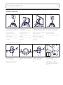
Headrest Operation
Articulating and Non-Articulating Headrests
B
C
A
B
A
C
AB
C
B
B
A
1. To install the headrest:
A. To loosen, turn the knob
on the back of the chair
counterclockwise.
B. Insert the headrest
through the slot in the top
of the backrest.
C. To secure, turn the knob
clockwise.
2. To adjust the height of
the headrest:
A. To loosen, turn the knob
on the back of the chair
counterclockwise.
B. Adjust the height of the
headrest.
C. To secure, turn the knob
clockwise.
3. To adjust the angle of the
headrest (Articulating only):
A. To loosen, turn the knob
on the back of the headrest
counterclockwise.
B. Adjust the position and
angle of the headrest.
C. To secure, turn the knob
clockwise.
4. To remove a headrest:
A. To loosen, turn the knob
on the back of the chair
counterclockwise.
B. Pull the headrest
completely out of the back.
Headrests with Forearm Supports
1. To attach forearm supports
on the headrest:
Insert the rod of the
forearm support into the
headrest until it clicks.
2. To use forearm supports:
Place forearms on the foam
pads.
3. To remove forearm
supports on headrest:
Pull the forearm support
out.
4. To adjust tightness of the
forearm support:
Tighten the set screw on
the bottom side of the
holding block by turning
clockwise with a 5/64" Allen
Wrench.

12 User Manual | MTI 721
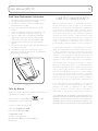
Electrical Lockout
The electrical lockout cuts power to all motors to eliminate possible EMI (electromagnetic interference) and RFI
(radio frequency interference). This switch also resets the circuit board.
1. To lock out control of the
chair:
A. Switch the toggle switch
to the o position (pointing
toward the backrest of the
chair).
2. To enable control of the
chair:
A. Switch the toggle switch
to the on position (pointing
toward the footrest of the
chair).
NOTICE/AVIS
The toggle switch will not lock out non-powered motion.
L’interrupteur à bascule ne sera pas verrouiller le mouvement non-motorisé.
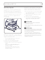
LOCK
STEER
FREE
STEERING MODE: When the left-hand locking bar is in the STEER position and the right-hand locking bar is in the
FREE or STEER position: the (3) Total Lock Casters will roll and swivel freely and the (1) Steering Caster will roll
but will not swivel. This mode is used for transport as the Steering Caster acts as a steering wheel to aid in easy
transport.
FREE MODE: When both oset locking bars are in the FREE position; all (4) casters will roll and swivel freely. This
position is used when you need to pull the chair away from an object in a perpendicular direction or turn the chair
with a zero radius.
LOCKED MODE: When both oset locking bars are in the LOCK position; all (4) casters will not roll or swivel. This
position is used to prevent unwanted movement of the chair.
Mobile Base Operation
The Low Boy mobile base is a factory installed option for the 721
Model chairs.
The two casters on the patient’s right side and the rear caster on
the patient’s left side of the chair are Total Lock Casters. The front
caster on the patient’s left side is the Steering Caster.
In the FREE or STEER position, the Total Lock Casters will roll and
swivel. In the LOCK position, the Total Lock Casters will not roll or
swivel.
In the STEER position, the Steering Caster will roll but not swivel.
In the FREE position, the Steering Caster will swivel and roll. In
the LOCK position, the Steering Caster will not roll or swivel.
There are three modes for the oset locking bars. See image on right.

User Manual | MTI 721 13
Swivel Base Operation
The swivel base is a factory installed option for the
721 Model chairs. See also “Controls” on page 10 of
this manual. Swivel mode is the condition when the
swivel lock is unlocked and the chair can swivel freely.
There are two methods to operate the swivel on the
721 Model chairs. Follow the step(s) below for the
desired method.
Method 1: Auto engage mode is a swivel mode which
will unlock the swivel for 6 seconds and automatically
engage the lock after 6 seconds.
1. Press the swivel button on the control and
release it within two seconds.
2. Swivel enters swivel mode for 6 seconds.
3. Swivel the chair to the desired location.
4. After 6 seconds, the swivel lock will automatically
engage.
• If the chair is in swivel mode and the swivel
button is pressed again, the swivel lock
immediately engages.
• If the chair is in swivel mode and any other
command button is pressed, the swivel lock
immediately engages.
Method 2: Press and hold mode is a swivel mode
where the swivel will unlock as long as you hold
down the swivel button on the control. Once you
release the swivel button, the swivel lock will engage.
1. Press and hold swivel button on the control for
longer than two seconds.
2. The chair enters swivel mode until the swivel
button is released.
3. Swivel the chair to the desired location.
4. The chair stays in swivel mode as long as the
swivel button is held down and immediately
engages swivel lock upon button release.
NOTICE/AVIS
The swivel will lock if the swivel is unlocked and
another button is pressed.
Le pivot se bloque si le pivot est déverrouillé et un autre
bouton est pressé.
NOTICE/AVIS
The swivel will unlock if the chair loses power. If power
is lost, install the swivel bolt removed in step 15 of the
Set-up instructions on page 9
Le pivot va déverrouiller si l’équipement perd son
alimentation. Si l’alimentation est perdue, installez le
boulon pivotant retiré à l’étape 15 des instructions de
configuration à la page 9.

14 User Manual | MTI 721
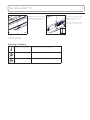
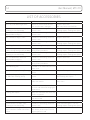
LIST OF ACCESSORIES
DESCRIPTION USE RESTRICTIONS
Accessory Rail Mounting Bracket Bracket to mount various devices
such as hyfrecators and lights
Requires Base Rails.
Not compatible with Bed Rails.
Arm, Deluxe 8-way 18" IV/Surgery
(Floating or seat mounted)
Provides an articulating surface for
patient’s arms
Seat mounted requires seat rails.
Floating requires Floating Arm Option.
Arm, Deluxe 8-way Back Rail
Mounted 24" IV/Surgery
Provides an articulating surface for
patient’s arms
Requires Back Rails
Arm, Hand/Arm Surgery Table Provides an articulating surface for
patient’s arms
Requires Back Rails
Arm, Hand/Forearm Procedure Table Provides an articulating surface for
patient’s arms
Seat mounted requires seat rails.
Floating requires Floating Arm Option.
Arm Sling, Patient Provides a sling for the patient’s arm
Arm, Standard 4-way Removable
Patient Arm (Floating and Seat Mtd)
Used by patient to rest their arms
during exams/procedures
Seat mounted requires seat rails.
Floating requires Floating Arm Option.
Arm, Standard 8-way, 18" IV/Surgery
(Floating or seat mounted)
Provides an articulating surface for
patient’s arms
Seat mounted requires seat rails.
Floating requires Floating Arm Option.
Arm, Standard 8-way Back Rail
Mounted 24" IV/Surgery
Provides an articulating surface for
patient’s arms
Requires Back Rails
Arms, Slide Back Floating Used by patient to rest their arms
during exams/procedures
Requires Floating Arm Option
Base Mounting Rail Provideds a rail mounted to the base
of the chair
Bed Rails, Swing Up/Down (Floating) Provides a vertical surface to secure
patient
Requires Floating Arm Option
Bed Rails, Swing Up/Down (Mounted
to Slide Back Floating Arms)
Provides a vertical surface to secure
patient
Requires Slide Back Floating Arms
and Floating Arm Option
Casters with individual locks Provides field installable casters to
make chair mobile
Not available on mobile or swivel
base chairs
Corded Hand Control w/Mount Provides an additional control for
the chair and mount for hanging the
hand control
Floating Arm Option Equips the chair with arms that stay
parallel to ground
Foot Control Provides a means to control the
chair with a foot
Hand Control Caddy, Flexible Used to hold a hand control Requires Seat or Base Rails
Hand/Forearm Procedure Table
(Floating or seat mounted)
Provides an articulating surface for
patient’s arms
Seat mounted requires seat rails.
Floating requires Floating Arm Option.
Headrest, Articulating Oval, Deep
Oval, Prosthetic, Round, Horseshoe/
Donut
Provides a dual articulating surface
with various pillow shapes/sizes to
support patient’s head

User Manual | MTI 721 15
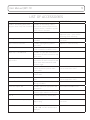
LIST OF ACCESSORIES
DESCRIPTION USE RESTRICTIONS
Headrest, Articulating w/Forearm
Supports; Oval, Deep Oval, Prosthetic
Provides an articulating surface
with various pillow shapes/sizes to
support patient’s head with supports
for a clinician’s forearms
IV Rod and Holder Provides an adjustable IV rod Mounts to various chair components.
Requires 2” post, 1” post, or base
mounting rail for mounting
Leveling Glides, 2” Provides taller leveling glides than
standard
Not available on mobile or swivel
base chairs
Light, Lumerus LED Exam Provides lighting during patient
procedures
Requires a 1” Post Accessory
Mayo Tray, Flexible Provides a tray for the placement of
small instruments and other items
Requires 2” Post
Mayo Tray, 1” Post Mounted Provides a 1” post with a tray for the
placement of small instruments and
other items
Mayo Tray, 1” Post Mounted with
Light mount
Provides a 1” post with a tray for the
placement of small instruments and
other items and a mount for a 42”
Lumerus Light
Mobile Caster Base Provides a field installable base with
casters and caster jacks to make
chair mobile
Not available with low boy mobile
base or swivel base chairs
Mobile Caster Base, Low Boy Changes a standard chair into a
mobile base
Factory installed
Mobile Caster Cart Provides a field installable mobile
base
Not available on low boy mobile
base or swivel base chairs
Monitor Tray, 2” Post Mounted Mounts a patient monitor for viewing
during procedures
Requires 2” Post
Outlet Kit, Duplex, 115V Provides power for appropriate 115V
accessories
Not available for 230V Chairs
Post, 1” Provides a post for mounting a 42”
Lumerus light and other accessories
Post, 2” Used to mount trays and IV poles
Power Cord with 90 degree plug, 3’ Provides a 3’ power cord with a 90
degree plug
Not available on mobile or swivel
base chairs
Rail Clamp Provides a clamp that can lock onto
1-1/8” x 3/8” size rails and accepts a
5/8” post
Requires rails

16 User Manual | MTI 721
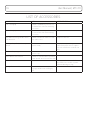
LIST OF ACCESSORIES
DESCRIPTION USE RESTRICTIONS
Rails, Back (set) Provides standard hospital rails to
the back of the chair for mounting
accessories
Rails, Seat (set) Provides standard hospital rails to
the seat of the chair for mounting
accessories
Removable Steering Handles, Back
Rail Mounted
Provides handles to move the chair
with mobile base
Requires back rails
Restraint Strap, Body with snaps or
Velcro®
Provides a strap to secure the
patient’s body
Strap with snaps mounts to seat
frame. Strap with Velcro® requires
seat rails and fastens around seat
rails.
Restraint Strap, Leg Provides a strap to secure the
patient’s legs
Slant Mount, Foot Control Provides a slanted surface to mount
a foot control at the rear of the chair
Swivel Base Allows chair to swivel Factory Installed. Not available with
any mobile base or with a power
cord with 90 degree plug.
Syringe Bracket Holder Provides a dovetail mount to attach
a syringe holder to an IV/Surgery
Arm
La page est en cours de chargement...
La page est en cours de chargement...
La page est en cours de chargement...
La page est en cours de chargement...
La page est en cours de chargement...
La page est en cours de chargement...
La page est en cours de chargement...
La page est en cours de chargement...
-
 1
1
-
 2
2
-
 3
3
-
 4
4
-
 5
5
-
 6
6
-
 7
7
-
 8
8
-
 9
9
-
 10
10
-
 11
11
-
 12
12
-
 13
13
-
 14
14
-
 15
15
-
 16
16
-
 17
17
-
 18
18
-
 19
19
-
 20
20
-
 21
21
-
 22
22
-
 23
23
-
 24
24
-
 25
25
-
 26
26
-
 27
27
-
 28
28


dans d''autres langues
- English: MTI 721 Owner's manual
Documents connexes
-
MTI 450W Le manuel du propriétaire
-
-
-
-
-
-
-
MTI Freedom Micro Ii Hs Manuel utilisateur
-
Autres documents
-
Invacare Jasmine Le manuel du propriétaire
-
-
-
Vermeiren Regina Manuel utilisateur
-
-
Evolution S-250 Manuel utilisateur
-
-
-
Hillrom O-PRSLH Manuel utilisateur