Quadrafire Castile Pellet Stove Le manuel du propriétaire
- Catégorie
- Poêles
- Taper
- Le manuel du propriétaire

1 February 11, 20197021-155H
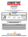
NOTICE: DO NOT DISCARD THIS MANUAL
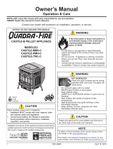
R
CASTILE-B PELLET APPLIANCE
MODEL(S):
CASTILE-MBK-B
CASTILE-CSB-B
CASTILE-PMH-B
Owner’s Manual
Operation & Care
INSTALLER: Leave this manual with party responsible for use and operation.
OWNER: Retain this manual for future reference.
Contact your dealer with questions on installation, operation, or service.
CAUTION
Tested and approved for wood pellets and shelled
corn only. Burning of any other type of fuel voids your
warranty.
NOTE
To obtain a French translation of this manual, please
contact your dealer or visit www.quadrare.com
Pour obtenir une traduction française de ce manuel, s’il
vous plaît contacter votre revendeur ou visitez
www.quadrare.com
CAUTION
Check building codes prior to installation.
• Installation MUST comply with local, regional, state
and national codes and regulations.
• Consult local building, re ofcials or authorities
having jurisdiction about restrictions, installation
inspection, and permits.
Installation and service of this appliance should be performed by
qualified personnel. Hearth & Home Technologies recommends
HHT Factory Trained or NFI certified professionals.
WARNING
If the information in these instructions is not
followed exactly, a re could result causing
property damage, personal injury, or death.
• Do not store or use gasoline or other ammable
vapors and liquids in the vicinity of this or any other
appliance.
• Do not over re - If appliance or chimney connector
glows, you are over ring. Over ring will void your
warranty.
• Comply with all minimum clearances to combustibles
as specied. Failure to comply may cause house re.
WARNING
HOT SURFACES!
Glass and other surfaces are hot during
operation AND cool down.
Hot glass will cause burns.
• Do not touch glass until it is cooled
• NEVER allow children to touch glass
• Keep children away
• CAREFULLY SUPERVISE children in same room as
replace.
• Alert children and adults to hazards of high
temperatures
• High temperatures may ignite clothing or other
ammable materials.
• Keep clothing, furniture, draperies and other
ammable materials away.

2 February 11, 20197021-155H
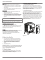
CASTILE FREESTANDING
CAUTION: HOT WHILE IN OPERATION DO NOT TOUCH, KEEP CHILDREN,
CLOTHING AND FURNITURE AWAY. CONTACT MAY CAUSE SKIN BURNS. SEE
NAMEPLATE AND INSTRUCTIONS. Operate this unit only with fuel hopper lid closed.
Failure to do so may result in emissions of products of combustion from the hopper
under certain conditions. Maintain hopper seal in good condition. Do not over fill the
hopper.
ATTENTION
:
CHAUD LORS DE L'OPÉRATION. NE PAS TOUCHER. GARDEZ LES ENFANTS ET LES VÊTEMENTS
LOIN DE L'ESPACE DÉSIGNÉ DE L'INSTALLATION. LE CONTACT PEUT CAUSER DES BRÛLURES À LA PEAU. VOIR
L'ÉTIQUETTE ET LES INSTRUCTIONS.
Opérez cet appareil uniquement avec le couvercle de la trémie fermé. Le défaut de ne pas
suivre les instructions peut résulter, sous certaines conditions, en une combustion des émissions des produits venant de la trémie. Ne
pas remplir la trémie trop pleine.
7014-197C
Report / Rapport
061-S77d-6.2
BARCODE LABEL
HF
Serial No. /
N
o
de série:
®
Castile Pellet Stove
Appareil de chauffage solide/de type de boulettes. Accepté dans l’installation dans les maisons mobiles. Cet appareil a été testé et enregistré pour i’usage dans les
Maisons Mobiles en accord avec OAR 814-23-9000 jusqu’à 814-23-909. OMNI-Test laboratories, Inc. a déterminé que cet appareil se conforme avec la norme de
l’Association Canadienne de normalisation (CSA) B415.1 ainsi que le Titre 40 du Code Fédéral de Régulations des États-Unis, partie 60, sous-partie AAA. Accréditations
OMNI-Test Laboratories : Le conseil Canadien des Normes (CCN/SCC), l’Institue des Standards Nationaux Américan (ANSI) et l’Agence de Protection Environmental
(EPA).
Testé à: ASTM E1509-04, ULC S627-00, ULC/ORD-C1482-M1990 Room Heating Pellet Burning Type, (UM) 84-HUD POUR USAGE AVEC LES BOULETTES DE
BOIS OU DE COMBUSTIBLE DE MAIS ÉCOSSÉ DES CHAMPS.
N’utiliser aucun autre genre de combustible puissance de Rendement: 38,700 Btu’s/hr. Puissance
l’appereil. Ne pas bloquer l’espace au dessous de l’appareil.
DANGER: Risque de décharge électrique. Déconnectez le dil électrique de la prise de contact avant le service.
Remplacez la vitre seulement avec une vitre céramique de 5 mm disponsible chez votre fournisseur.
Pour allumer, monter la température du thermostat en dessous de la température de oa pièce. Pour des instructions supplémentaires, référez vous au manel du
propriétaire. Gardez la porte d’ouverture et la porte des cendres fermées hermétiquement durant l’opération.
PRÉVENTION DES FEUZ DE MASON - Installez et utilisez en accord avec les instructions d’installation et d’opération du fabricant. Contactez le bureau de la constuction
ou le bureau des incendies au sujet des restrictions et des inspections d’installation dans votre voisinage. Ne pas obstruex l’espace en dessous de l’appareil.
AVIS - Pour les Maisons Mobiles: Ne pas installer dans une chambre à coucher. Un tuyau extérieu de combustion d’air doit être maintenue intacte.
Référez vous aux instructions de fabricant et des codes locaux pour les précautions requises pour passer une cheminée à travers un mur ou un plafond combustibles, et
les compemsations maximums. Inspectez et nettoyez la cheminée fréquemment. Ne pas connecter cet appareil à une cheminée servant un autre appareil. Utilisez systèm
de ventilation “L” ou “P
L” diamètre 76mm ou 102mm.
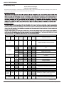
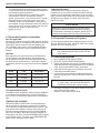
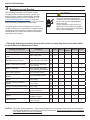
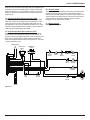
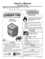
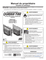
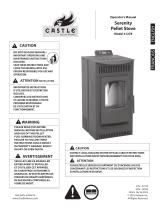
MINIMUM CLEARANCES TO COMBUSTIBLE MATERIALS
Note 1: In residential installations, when using Perts 811-0890, (3” - 3” Top Vent Adapter) and 812-3570 (3” - 6” Offset Adapter), 24 gauge
Note 1: Dans les installations résidentielles. Lorsque les pièces 811-0890, (dessus de l’adapteur 76mm - 76mm) et 812-3570 (dessus de
l’adapteur 76mm - 152mm), un tuyau connecteur de 6” pour mur simple de calibre 24 peut être utilisé.
Note 2: In manufactured home installation, when using Part 811-0890, (3” - 3” Top Vent Adapter) and (3” - 6” Offset Adapter), use listed
Note 2: Pour l‘utilisation dans les maisons prèfabriquées, lorsque les pièces 811-0860, (dessus de l’daptateur d’ventilation 76mm - 76mm)
et 812-3570 (le ressaut de l’adapteur 76m - 152mm), utilisez un tuyau connecteur evregistré pour mur double. Un assemblage d’air extérieur
(pièce 811-0872), doit être utilisé pour l’installation dans les maison préfabriquées.
C
C
A
B
“B” is to Cast Top
(“B” du haut)
D
E
“E” is to Cast Top
(“E” du haut)
F
F
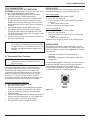
ESPACES LIBRES MINIMUM DES MATÉRIAUX COMBUSTIBLES:
A Back Wall to Stove / Mur Arrière du poêle 2” / 51mm
B Side Wall to Cast Top / Mur De Côté du haut 6” / 152mm
Corner Installation / Installation du Coin:
C Side Wall / Mur De Côté 2” / 51mm
Vertical 3 in. - 6 in. Adapter Kit (Part #812-3570 Installation / Unassemblage Pour
Adapteur 76mm - 152mm (Pièce 812-3570 Pour Installation verticale:
D Back Wall to Flue Pipe / Mur Arrière tuyau rigide 3” / 76mm
E Side Wall to Cast Top / Mur De Côté du haut 6” / 152mm
Corner Installation with Vertical Adapter Kit / Installation du coin avec un
assemblage d’adapteur verticale:
F Side Wall / Mur De Côté 2” / 51mm
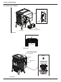
Alcove Installation / Installation de l’alcove:
Min. Alcove Height / Une hauteur minimum de l’alcove: 43” / 1092mm
Min. Alcove Side Wall / Une hauteur minimum mur de côté de l’alcove: 6” / 152mm
Max. Alcove Depth / La profondeur maximum de l’alcove: 36” / 914mm
G G
I
H*
USA
G = 6” / 152mm
H* = 2” / 51mm
I = 6” / 152mm
Canada
G = 203mm
H* = 51mm
I = 457mm
FLOOR PROTECTION / PROTECTION DU SOL
pipe when installed with horizontal venting or under the Top
Vent Adapter with vertical installation. Recommended in USA;
Required in Canada.
Floor protection must be non-combustible material, extending
beneath heater and to the front/sides/rear as indicated. Measure
front distance (I) from the surface of the glass door.
*La protection du sol non combustible doit se prolonger sous la
conduite de fumée lorsqu’elle est installée avec une ventilation
horizontale ou sous l’adaptateur de ventilation supérieure avec
une installation verticale. Recommandé aux USA; Obligatoire
au Canada.
La protection du sol doit être incombustible, s’étendant sous le
radiateur et à l’avant / aux côtés / à l’arrière comme indiqué.
Mesurer la distance avant (I) à partir de la surface de la porte
vitrée.
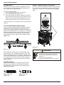
7021-131_R6
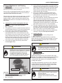
Date of Manufacture / Date de fabrication:
2017 2018 2019 JAN FEB MAR APR MAY JUN JUL AUG SEP OCT NOV DEC
Manufactured by / Fabriqué par: Hearth and Home Technologies 352 Mountain House Road, Halifax PA 17032
U.S. Environmental Protection Agency
A Method 28 & 5G. Not approved for sale after May 15, 2020
This wood heater needs periodic inspection and repair for proper operation. Consult the owner’s Manual for further information. It is against federal
regulations to operate this wood heater in a manner inconsistent with operating instructions in this manual.
DO NOT REMOVE THIS LABEL / NE PAS ENLEVER L’ETIQUETTE
Made in the U.S.A. of US and imported parts. / Fabriqué aux États-Unis-d’Amérique par des pièces d’origine américaine et pièces importées.
Listed solid fuel Room Heater/Pellet Type. Also suitable for Mobile Home Installation. This appliance has been tested and listed for use in
Manufactured Homes in accordance with OAR 814-23-9000 through 841-23-909. OMNI-Test Laboratories, Inc. has determined that this
appliance complies with Canadian Standards Association (CSA) B415.1 and Title 40 of the U.S. Code of Federal Regulations, Part 60, SubPart
AAA.OMNI-Test Laboratories Accreditations: The Standards Council of Canada, the American National Standards Institute, and the U.S.
Environmental Protection Agency.
Tested to: ASTME E1509-04, ULC S627-00, ULC/ORD-C1482-M1990 Room Heating Pellet Burning Type, (UM) 84-HUD FOR USE ONLY WITH
PELLETIZED WOOD OR SHELLED FIELD CORN FUEL. Do not use any other type of fuel.
Input Rating: 38,700 Btu’s/hr Electrical Rating: 115 VAC, 60 Hz, Start 4.1 Amps, Run 1.1 Amps. Route power cord away from unit. Do not route
cord under or in front of appliance. Do not obstruct the space beneath the heater.
DANGER: Risk of electrical shock. Disconnect power supply before servicing. Replace glass only with 5mm ceramic available from your
dealer. To start, set thermostat above room temperature, the stove will light automatically. To shutdown, set thermostat to below room
temperature. For further instruction refer to owner’s manual. Keep viewing and ash removal doors tightly closed during operation.
PREVENT HOUSE FIRES - Install and use only in accordance with manufacturer’s installation and operating instructions. Contact local
building or fire officials about restrictions and inspections in your area.
WARNING - FOR MOBILE HOMES: Do not install appliance in a sleeping room. An outside combustion air inlet must be provided. The structural
integrity of the mobile home floor, ceiling and walls must be maintained.
DO NOT CONNECT THIS UNIT TO A CHIMNEY SERVING ANOTHER APPLIANCE. Use a 3 in o
r 4 in diameter type”L” or “PL” venting system.
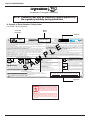
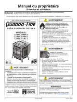
A. Sample of Serial Number / Safety Label
LOCATION: Back of Appliance
Serial No.
SAMPLE
Model
Name
Test Lab &
Report No.
Mfg. Date
NOTE: Clearances may only be reduced by means approved by
the regulatory authority having jurisdiction
and Welcome to the Quadra-Fire Family!

3February 11, 2019 7021-155H
CASTILE FREESTANDING
TABLE OF CONTENTS
Safety Alert Key:
• DANGER! Indicates a hazardous situation which, if not avoided will result in death or serious injury.
• WARNING! Indicates a hazardous situation which, if not avoided could result in death or serious injury.
• CAUTION! Indicates a hazardous situation which, if not avoided, could result in minor or moderate injury.
• NOTICE: Indicates practices which may cause damage to the appliance or to property.
A. Sample of Serial Number / Safety Label ......... 2
B. Warranty Policy ............................ 4
1 Listing and Code Approvals ..............7
A. Appliance Certication....................... 7
B. BTU & Efciency Specications ............... 7
C. Glass Specications ........................ 8
D. Electrical Rating ........................... 8
E. Mobile Home Approved ...................... 8
F. Sleeping Room ............................ 8
G. California - Prop65 ......................... 8
2 Operating Instructions .......................9
A. Fire Safety ................................ 9
B. Non-Combustible Materials ................... 9
C. Combustible Materials....................... 9
D. Fuel Material and Fuel Storage................ 9
E. Before Your First Fire ...................... 10
F. Filling the Hopper.......................... 10
G. General Operating Information ............... 10
H. Starting Your First Fire ..................... 11
I. Fire Characteristics......................... 11
J. Feed Rate Adjustment Instructions ............ 11
K. Ignition Cycles ............................ 12
L. Restarting the Appliance .................... 12
M. Clear Space ............................. 12
N. Thermostat Controls ....................... 13
O. Thermostat Setup Options .................. 13
P. Thermostat Operation Instructions............. 14
Q. Thermostat Temperature Programs ........... 14
R. Thermostat Other Features.................. 15
S. Thermostat Battery Replacement ............. 16
T. Frequently Asked Questions ................. 17
3 Maintenance and Service .................18
A. Quick Reference Maintenance Chart .......... 18
B. General Maintenance and Cleaning ........... 19
C. Soot or Creosote Fire Awareness ............. 22
D. High Ash Fuel Content Maintenance........... 22
4 Troubleshooting Guide .....................23
5 Service Parts Replacement ..............26
A. Glass Replacement - Door Assembly .......... 26
B. Igniter Replacement ....................... 26
C. Blower Replacement ....................... 27
D. Bafe & Brick Set Removal .................. 28
E. Bafe & Brick Set Installation ................ 29
6 Reference Materials ..........................30
A. Component Functions ..................... 30
B. Component Locations ...................... 32
C. Service and Maintenance Log................ 33
D. Exploded Drawings ........................ 34
E. Service Parts ............................. 35
Quadra-Fire is a registered trademark of Hearth & Home Technologies.

4 February 11, 20197021-155H
CASTILE FREESTANDING
B. Warranty Policy
4021-645J • 08-03-171
Hearth & Home Technologies
LIMITED LIFETIME WARRANTY
Hearth & Home Technologies, on behalf of its hearth brands (“HHT”), extends the following warranty for HHT gas, wood, pellet and
electric hearth appliances that are purchased from an HHT authorized dealer.
WARRANTY COVERAGE:
WARRANTY PERIOD:
distributor, whichever occurs earlier. However, the warranty shall commence no later than 24 months following the date of product
is produced in the following table.
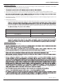
Parts Labor Gas Pellet Wood Electric Venting Components Covered
X X
Igniters, auger motors, electronic components, and
glass
X X X
Factory-installed blowers
X
Molded refractory panels
X
Ignition Modules
X
Firepots, burnpots, mechanical feeders/auger
assemblies
X
Vent Free burners, Vent Free ceramic fiber logs,
Aluminized Burners
X X
Castings and Baffles
6 years 3 years
X
Catalyst - limitations listed
7 years 3 years
X X
Manifold tubes, HHT chimney and termination
10 years 1 year
X
Burners, logs and refractory
Limited
Lifetime
3 years
X X X
Firebox and heat exchanger, Grate and Stainless
Steel Burners, FlexBurn® System (engine, inner
cover,access cover and fireback)
X X X X X
All replacement parts beyond warranty period
Warranty Period HHT Manufactured Appliances and Venting
All parts and material except as covered by
Conditions, Exclusions, and Limitations listed
X X X
2 years
3 years
1 Year
90 Days
5 years 1 year
xX

5February 11, 2019 7021-155H
CASTILE FREESTANDING
4021-645J • 08-03-172
WARRANTY CONDITIONS:
• This warranty only covers HHT appliances that are purchased through an HHT authorized dealer or distributor. A list of HHT
authorized dealers is available on the HHT branded websites.
•
• This warranty is only valid in the country in which the HHT authorized dealer or distributor that sold the appliance resides.
• Contact your installing dealer for warranty service. If the installing dealer or distributor is unable to provide necessary parts, contact
other than the dealer from whom you originally purchased the product.
• Check with your dealer in advance for any costs to you when arranging a warranty call. Travel and shipping charges for parts are not
covered by this warranty.
• Limited Catalyst Warranty
o For wood burning products containing a catalyst, the catalyst will be warranted for a six-year period as follows: if the original
o From 37 to 72 months a pro-rated credit will be allowed against a replacement catalyst and labor credit necessary to install
Amount of Time Since Purchase Credit Towards Replacement Cost
0 - 36 Months 100%
37 - 48 Months 30%
49 - 60 Months 20%
61 - 72 Months 10%
o Any replacement catalyst will be warranted under the terms of the catalyst warranty for the remaining term of the original
WARRANTY EXCLUSIONS:
This warranty does not cover the following:
•
•
• Repair or replacement of parts that are subject to normal wear and tear during the warranty period are not covered. These parts
•
this noise are not covered by this warranty.
•
•
•
•

6 February 11, 20197021-155H
CASTILE FREESTANDING
4021-645J • 08-03-173
This warranty is void if:
•
•
• There is any damage to the appliance or other components due to water or weather damage which is the result of, but not limited
LIMITATIONS OF LIABILITY
•
have other rights, which vary from state to state. EXCEPT TO THE EXTENT PROVIDED BY LAW, HHT MAKES NO EXPRESS WARRANTIES
OTHER THAN THE WARRANTY SPECIFIED HEREIN. THE DURATION OF ANY IMPLIED WARRANTY IS LIMITED TO DURATION OF THE
EXPRESSED WARRANTY SPECIFIED ABOVE.

7February 11, 2019 7021-155H
CASTILE FREESTANDING
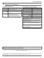
Model
Castile Pellet Appliance
Laboratory OMNI Test Laboratories, Inc.
Report No. 061-S-77d-6.2
Type
Solid Fuel Room Appliance/Pellet Fuel
Burning Type
Standard
ASTM E1509-04, ULC S627-00 and
ULC/ORD-C1482-M1990 Room
Appliance Pellet Fuel Burning type and
(UM) 84-HUD, Mobile Home Approved.
1 Listing and Code Approvals
A. Appliance Certication
B. BTU & Efciency Specications
NOTICE: This installation must conform with local codes. In the absence of local codes you must comply with the ASTM
E1509-04, ULC S627-00, (UM) 84-HUD and ULC/ORD-C-1482.
EPA Certication #: 940-14
EPA Certied Emissions: 1.8 grams per hour
*LHV Tested Efciency: N/A
**HHV Tested Efciency: N/A
***EPA BTU Output: 8,500 to 28,200 / hr.
****BTU Input: 11,600 to 38,700 / hr.
Vent Size: 3, 4 or 6 inches, “L” or “PL”
Hopper Capacity: 45 lbs.
Fuel Wood Pellets
* Weighted average LHV efciency using data collected
during EPA emissions test.
**Weighted average HHV efciency using data collected
during EPA emissions test.
***A range of BTU outputs based on EPA Default
Efciency and the burn rates from the low and high EPA
tests.
****Based on the maximum feed rate per hour multiplied
by approximately 8600 BTU’s which is the average BTU’s
from a pound of pellets.
The Quadra-Fire Castile Pellet Appliance meets the U.S. Environmental Protection Agency’s emission limits for pellet
appliances sold after May 15, 2015.
This pellet appliance needs periodic inspection and repair for proper operation. It is against federal regulations to operate
this pellet appliance in a manner inconsistent with operating instructions in this manual.

8 February 11, 20197021-155H
CASTILE FREESTANDING
NOTE: Hearth & Home Technologies, manufacturer of this
appliance, reserves the right to alter its products,
their specications and/or price without notice.
Improper installation, adjustment, alteration, service or
maintenance can cause injury or property damage.
For assistance or additional information, consult a qualied
installer, service agency or your dealer.
C. Glass Specications
This appliance is equipped with 5mm ceramic glass.
Replace glass only with 5mm ceramic glass. Please
contact your dealer for replacement glass.
E. Mobile Home Approved
• This appliance is approved for mobile home
installations when not installed in a sleeping room and
when an outside combustion air inlet is provided.
• The structural integrity of the mobile home oor, ceiling,
and walls must be maintained.
• The appliance must be properly grounded to the frame
of the mobile home and use only Listed pellet vent
Class “L” or “PL” connector pipe.
• Outside Air Kit, part OAK-ACC must be installed in a
mobile home installation.
D. Electrical Rating
115 VAC, 60 Hz, Start 5 Amps, Run 1.25 Amps
F. Sleeping Room
When installed in a sleeping room it is recommended that
3ft of vertical be installed prior to horizontally exiting the
room and a smoke/CO alarm be installed in the bedroom.
The size of the room must be at least 50ft³ per 1,000 Btu/hr
stove input, if the stove exceeds the room size, out air must
be installed.
G. California - Prop65
WARNING
This product and the fuels used to operate this product (wood), and
the products of combustion of such fuels, can expose you to
chemicals including carbon black, which is known to the State of
California to cause cancer, and carbon monoxide, which is known to
the State of California to cause birth defects or other reproductive
harm. For more information go to: WWW.P65Warnings.ca.gov
WARNING
Fire Risk.
Hearth & Home Technologies disclaims any
responsibility for, and the warranty will be
voided by, the following actions:
• Installation and use of any damaged appliance.
• Modication of the appliance.
• Installation other than as instructed by Hearth &
Home Technologies.
• Installation and/or use of any component part not
approved by Hearth & Home Technologies.
• Operating appliance without fully assembling all
components.
• Operating appliance without legs attached (if
supplied with appliance).
• Do NOT Over re - If appliance or chimney connector
glows, you are over ring.
Any such action that may cause a re hazard.

9February 11, 2019 7021-155H
CASTILE FREESTANDING
User Guide
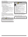
2 Operating Instructions
D. Fuel Material and Fuel Storage
Pellet fuel quality can greatly uctuate. This appliance has
been designed to burn a wide variety of fuels, giving you
the choice to use the fuel that is most economical in your
region.
Hearth & Home Technologies strongly recommends only
using Pellet Fuel Institute (PFI) certied fuel.
WARNING
Fire Risk.
• Do not operate appliance before reading
and understanding operating instructions.
• Failure to operate appliance properly may
cause a house re.
A. Fire Safety
To provide reasonable re safety, the following should be
given serious consideration:
• Install at least one smoke detector on each oor of
your home.
• Install at least one carbon monoxide detector on each
oor of your home.
• Locate smoke detector away from the heating
appliance and close to the sleeping areas.
• Follow the smoke detector manufacturer’s placement
and installation instructions and maintain regularly.
• Follow the carbon monoxide manufacturer’s placement
and installation instructions and maintain regularly.
• Conveniently locate a Class A re extinguisher to
contend with small res.
• In the event of a hopper re:
• Evacuate the house immediately.
• Notify re department.
Visit www.quadrare.com/shopping-tools/videos to view
product and use & care videos.
B. Non-Combustible Materials
Material which will not ignite and burn, composed of any
combination of the following:
C. Combustible Materials
Material made of/or surfaced with any of the following
materials:
- Steel
- Plaster
- Brick
- Iron
- Concrete
- Tile
- Glass
- Slate
Materials reported as passing ASTM E 136, Standard
Test Method for Behavior of Metals, in a Vertical Tube
Furnace of 750° C.
- Wood
- Compressed Paper
- Plant Fibers
- Plastic
- Plywood/OSB
- Sheet Rock (drywall)
Any material that can ignite and burn: ame proofed or not,
plastered or non-plastered.
Do not burn fuel that contains an additive; (such as
soybean oil).
• May cause hopper res
• Damage to product may result
Read the ingredients list on the package.
CAUTION!
Fuel Material
• Made from sawdust or wood by-products
• Depending on the source material it may have a high or
low ash content.
Higher Ash Content Material
• Hardwoods with a high mineral content
• Fuel that contains bark
• Standard grade pellets, high ash pellets, corn and other
biomass fuels
Lower Ash Content Material
• Most softwoods
• Fuels with low mineral content
• Most premium grade pellets
Corn
• Moisture content must be 15% or less
• Corn must be free of debris. Never burn corn straight
from the eld. It will clog the auger mechanism.
• Corn with excessive grain dust must be screened by
sifting with 3/16 (4.76mm) inch mesh screening
• Do no sue corn that contains additives such as oils or
means or has been chemically treated with pesticides.
It will void your warranty and destroy the exhaust
system.
Clinkers
Minerals and other non-combustible materials such as sand
will turn into a hard, glass-like substance called a clinker
when heated in the re pot.
Trees from different areas will vary in mineral content. That
is why some fuels produce more clinkers than others.
Moisture
Always burn dry fuel. Burning fuel with high moisture
content takes heat from the fuel and tends to cool the
appliance, robbing heat from your home. Damp pellet fuel
can clog the feed system.

10 February 11, 20197021-155H
CASTILE FREESTANDING
G. General Operating Information
1. Thermostat Calls For Heat
The appliance is like most modern furnaces; when the
thermostat calls for heat, your appliance will automatically
light and deliver heat. When the room is up to temperature
and the thermostat is satised, the red call light will go off
and the appliance will shut down.
2. Heat Output Controls
This appliance is equipped with a heat output control switch
that has three settings or burn rates; low, medium and
high. The appliance will turn on and off as the thermostat
demands. When the thermostat calls for heat, the
appliance will start up at the burn rate for which it is set. If
the appliance is set at one of the lower settings, it will run
quieter but take longer to heat up an area than if it were set
at a higher burn rate. Regardless of the burn rate, when
the area is warm enough to satisfy the thermostat, the
appliance will shut off.
Tested and approved for wood pellets and shelled corn.
Burning of any other type of fuel voids your warranty.
CAUTION
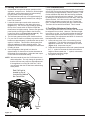
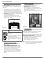
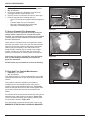
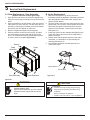
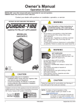
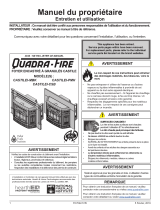
Figure 10.1
E. Before Your First Fire
1. First, make sure your appliance has been properly
installed and that all safety requirements have been
met. Pay particular attention to the re protection,
venting and thermostat installation instructions.
2. Double check that the ash drawer and rebox are
empty!
3. Close the front door.
IMPORTANT DETAIL: The tip of the thermocouple must
be in contact with the inside end of the thermocouple
cover or missed ignitions can occur.
High
Med
Low
Heat Output Switch
Reset Button
Reset
Button
Size
• Pellets are either 1/4 inch or 5/16 inch (6-8mm) in
diameter
• Length should be no more that 1-1/2 inches (38mm)
• Pellet lengths can vary from lot to lot from the same
manufacturer
• Due to length variations, the ame height (feed rate)
may need adjusting occasionally.
Performance
• Higher ash content requires the ash drawer to be
emptied more frequently
• Hardwoods require more air to burn properly
• Premium wood pellets produce the highest heat output.
• Burning pellets longer than 1-1/2 inches (38mm) can
cause an inconsistent fuel feed rate and/or missed
ignitions.
Changing to Different Fuel Type
• Empty the hopper of the previous fuel
• Thoroughly vacuum hopper before lling with the new
fuel
The burn rate, BTU content and heat output will all vary
depending on the fuel selected.
Storage
• Wood pellets should be left in their original sealed bag
until using to prevent moisture absorption.
Do not store any pellet fuel within the clearance
requirements or in an area that would hinder routine
cleaning and maintenance.
F. Filling the Hopper
Open the hopper lid by lifting the handle. Fill the hopper
with fuel. Close the hopper lid. The unit will not feed with
the hopper lid open and the re will go out.

11February 11, 2019 7021-155H
CASTILE FREESTANDING
H. Starting Your First Fire
1. A thermostat is required for proper operation of this
appliance, except for corn. At this time, ll the hopper
with pellets, set the thermostat to its lowest setting.
Plug the power cord into nearby outlet.
2. The exhaust blower will stay on for approximately 18
minutes even though the thermostat is not calling for
heat. This is normal.
3. L
ocate the heat output control switch mounted on
the back of the appliance in the upper right corner
(Figure 11.1). Turn it to the “high” setting by pushing
the top of the control switch in and then adjust the
thermostat to its highest setting. Remove the right side
panel and the red call light located to the left of the
control box will be on (Figure 10.2 on page 10). This
indicates the thermostat is calling for heat.
4. The fuel feed system and the igniter should
now
be on.
5. For your rst re it will be necessary to press the reset
button once approximately 2 minutes after start up and
again in 5 minutes. This will ll the feed system and
allow the appliance to begin dropping pellets. The
appliance will continue to run as long as the thermostat
is calling for heat.
6. Once the appliance has ignited, let it burn for
approximately 15 minutes, then set the thermostat to
the desired room temperature. Adjust the heat output
control switch to the desired setting.
NOTE: We recommend the use of a 50-50 blend of corn
and wood pellets. The only change in operation is
that the feed rate may require a slight adjustment.
If the appliance is running all of the time, 100%
corn will work after the re has been started using
wood pellets.
I. Fire Characteristics
A properly adjusted re with the heat output control switch
set on “high” has a short active ame pattern that extends
out of the re pot approximately 4 inches (102mm). If the
re has tall ames with black tails and seems somewhat
lazy, the feed rate will need to be reduced. This is done
by sliding the fuel adjustment control rod down, which will
reduce the feed. If the re is not 4 inches (102mm) tall,
slide the fuel adjustment control rod up to increase the
feed. A medium and low setting will give a shorter ame.
The ame will rise and fall somewhat. This is normal.
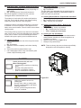
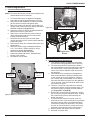
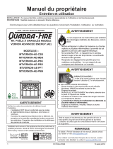
J. Feed Rate Adjustment Instructions
The feed adjustment control rod is factory set, and should
be adequate for most fuels. However, if the flame height
is too high or too low, you will need to adjust the feed rate.
Wait until the appliance has been burning for 15 minutes
before making your adjustments and a
llow 15 minutes for
feed adjustment to take effect.
1. Loosen the set screw 1/4 to 1/2 turn during set-up
of appliance. This will allow movement of the feed
adjustment control rod. Do not re-tighten set screw
(Figure 11.2). Loosen the wing nut.
2. Adjust the feed adjustment control rod upward towards
the “+” symbol to increase the feed rate and ame
height or down towards the “-” symbol, to decrease
the feed rate and ame height.
3. Re-tighten the wing nut.
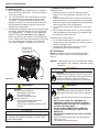
Figure 11.2
Thumb Screw
Set Screw
Feed Adjustment
Control Rod
Increase
Decrease
Figure 11.1
Red Call Light is
located on top of
Junction Box behind
the Control Box.
Control
Box

12 February 11, 20197021-155H
CASTILE FREESTANDING
HOT WHILE IN OPERATION. KEEP CHILDREN,
CLOTHING AND FURNITURE AWAY. CONTACT MAY
CAUSE SKIN BURNS.
CAUTION
Figure 12.1
Red Call Light is
located on top of
Junction Box behind
the Control Box.
Control
Box
K. Ignition Cycles
1. At the beginning of each ignition cycle, it is normal to
see some smoke in the rebox. The smoke will stop
once the re starts.
2. The convection blower will automatically turn on after
your appliance has been burning for approximately
10 minutes. This blower transfers heat from your
appliance into the room, and will continue to run after
the thermostat has stopped calling for heat until the
appliance has cooled down.
3. Occasionally the appliance may run out of fuel and shut
itself down. When this happens, the red call light will
be on (Figure 12.1). To restart it, ll the hopper and
press the reset button (See Figure 10.1, page 10).
When you press the reset button the red call light will
go out. Release the button and the light will come back
on. You should see a re shortly. If not, follow the
instructions on page 9, of “Starting Your First Fire”.
Fire Risk
Do NOT operate appliance:
• With appliance door open.
• Fire pot oor open.
• Cleaning slide plates open.
Do NOT store fuel:
• Closer than required clearances to
combustibles to appliance
• Within space required for loading or ash
removal.
WARNING
M. Clear Space
Mantel:
Avoid placing candles and other heat-sensitive
objects on mantel or hearth. Heat may damage these
objects.
NOTICE: Clearances may only be reduced by means
approved by the regulatory authority having
jurisdiction.
Fire Risk.
Keep combustible materials, gasoline and other
ammable vapors and liquids clear of appliance.
WARNING
• Do NOT store ammable materials in the appliance’s
vicinity.
• DO NOT USE GASOLINE, LANTERN FUEL,
KEROSENE, CHARCOAL LIGHTER FLUID OR
SIMILAR LIQUIDS TO START OR “FRESHEN UP”
A FIRE IN THIS APPLIANCE.
• DO NOT BURN GARBAGE OR FLAMMABLE
FLUIDS SUCH AS GASOLINE, NAPHTHA OR
ENGINE OIL.
• DO NOT USE CHEMICALS OR FLUIDS TO START
THE FIRE.
• Keep all such liquids well away from the appliance
while it is in use.
• Combustible materials may ignite.
Fire Risk.
Do NOT place combustible objects in front of the
appliance. High temperatures may ignite clothing,
furniture or draperies. Maintain a minimum
clearance of 3 feet (914mm) in front of appliance.
WARNING
L. Restarting the Appliance
Restart Process
1. When the unit has run out of fuel and the “empty
hopper” error code illuminates, add pellet fuel to the
hopper.
2. Dump the ashes and clinkers built up in the re pot by
pulling the ash dump removal handle out several times.
Make sure clinkers have dropped into the ash pan then
return the handle to fully closed position.
3. Turn the dial control to OFF and then up to high 2X to
prime.
4. After seeing pellets drop then turn to desired setting to
reset the appliance control system. The appliance will
then being its startup sequence.
Restarting After a Power Failure
1. For an electrical disruption the appliance will start on
its own without need for priming - providing the control
system is asking for heat.
2. The appliance will always go through a normal
shutdown sequence before restarting.

13February 11, 2019 7021-155H
CASTILE FREESTANDING
N. Thermostat Controls
TEMPERATURE (HEAT / OFF) SWITCH:
Set this switch to HEAT to control your appliance. The off
position will disable the appliance.
SET (MULTI- FUNCTION) SLIDE SWITCH:
This provides easy access to common settings, and should
always remain in RUN unless items are being adjusted.
NOTE: When thermostat is set to “Manual” non-
programmable mode, all positions of the SET slide
switch will act like RUN.
UP / DOWN BUTTONS:
The UP and DOWN buttons are used to control the set
temperature, or adjust any other on-screen items. An items
ashing, is the item currently being adjusted.
HOLD BUTTON:
This button activates and deactivates the manual
Temperature HOLD feature, which maintains a xed set
temperature indenitely without following a program routine.
COPY BUTTON:
This is used to copy temperature program items from one
day to the next. Also used to to access the menu setup.
NEXT BUTTON:
This is used when setting items such as software options,
and temperature programs when they are ashing on the
screen. Pressing the NEXT button will cycle through which
item is ashing.
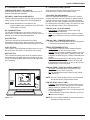
Figure 13.1
O. Thermostat Setup Options
Setup options for how the thermostat will function are
performed using a menu on the display screen.
TO ACCESS THE SETUP MENU:
Move the TEMPERATURE switch into the OFF position,
and then hold down the COPY button for approximately 5
seconds until the screen changes. The menu will always
start with item #01, and is advanced to each following item
by a single press of the NEXT button. The options for each
item are changed using the UP or DOWN buttons.
ITEM #01 (CLK = CLOCK FORMAT):
• 12Hr, default: This displays the clock times using
standard AM and PM values.
• 24Hr: This displays the clock times using the military-
time format (example 22:00 hours, without using AM or
PM).
ITEM #02 (TMP = TEMPERATURE SCALE):
• F, default: Shows all temperature values in Fahrenheit.
• C: Shows all temperature values Celsius.
ITEM #03 (PROGRAMMING STYLE):
• 7 Day, default: This style uses a separate program
routine for each of the 7 days in the week.
• 5/2 Day: This style uses a weekday program routine for
Monday, Tuesday, Wednesday, Thursday, Friday, and
a separate weekend program routine for Saturday and
Sunday.
• Manual Non-Programmable: In this setting, there are
no program routines for the thermostat to follow and
the temperature control will be set only by the UP and
DOWN buttons on the front panel.
ITEM #04 (PERD = EVENT OR PERIOD QUANTITY):
• 4P, default: Thermostat uses four Events per day
(called MORN, DAY, EVE, and NITE).
• 2P: The thermostat uses two Events per day (called
DAY and NITE).
NOTE: Event or Period Quantity feature is not accessible
during Manual Non-Programmable mode.
ITEM #07 (DLAY = DELAY TIME):
• 5, default: Thermostat waits 5 minutes before turning
the system back on after it was last run. This internal
delay prevents the appliance from turning on too
quickly after shutting down. The 5 minute setting is ne
for most applications.
• 2: Same operation as above but reduced to 2 minutes
between state changes.
NOTE: There is no delay available when the thermostat is
manually turned up and down.

14 February 11, 20197021-155H
CASTILE FREESTANDING
ITEM #08 (TEMPERATURE DIFFERENTIAL):
• The thermostat works by turning your heating system
on and off whenever the room temperature varies from
the desired set-point temperature.
• Use the UP/DOWN buttons to change the number
value between 1 and 9. Generally your system
should cycle on about 3 to 6 times per hour. A smaller
differential number makes the system cycle more
frequently, so the room temperature is more precise
and constant. A larger differential number will make the
system remain on for a longer duration each time and
decreases the number of cycles per hour.
• Default is set to 4.
Figure 14.1
Event Time Temperature
MORN 6:00 AM 70°F (21°C)
DAY 8:00 AM 62°F (17°C)
EVE 6:00 PM 70°F (21°C)
NITE 10:00 PM 62°F (17°C)
P. Thermostat Operation Instructions
SET DAY AND TIME:
Place the SET switch into the DAY/TIME position. With the
day ashing press UP or DOWN to set the day or the week.
Press NEXT and the clock time will start ashing. Use
UP or DOWN to set the time; verify the AM/PM indicator
is correct. Return the SET switch to RUN position when
nished.
HEATING:
Basic operation of the thermostat can be obtained with
the SET switch in the RUN position. The temperature
can be adjusted using the UP and DOWN buttons. When
the thermostat is rst powered on, it will follow a default
temperature routine that is preset from the factory (Figure
14.1).
LCD DISPLAY BACK LIGHT:
The display screen is lighted to assist viewing at nighttime,
or in locations with low light levels. Press any button on
the front panel to activate the approximate 10 second back
light.
TEMPERATURE OVERRIDE:
While thermostat is in RUN mode, the set temperature
can be temporarily changed by pressing UP or DOWN.
The temporarily changed set temperature will return to the
programmed value stored in memory when start time of
the next upcoming scheduled event is reached (MORN,
DAY, EVE, OR NITE). While the temporary changed set
temperature is in effect, the word OVERRIDE will be shown
on the display screen. To cancel, move TEMPERATURE
switch to OFF and back to HEAT again.
TEMPERATURE HOLD:
Temperature hold is used for maintaining a xed set
temperature; once a HOLD is initiated, the thermostat will
maintain the set temperature indenitely. To enter a HOLD
state, press the HOLD button one time and the word HOLD
will appear on the display. To cancel, press the HOLD
button once again.
STATIC NOTICE
Thermostat is protected against normal static electric
discharges, however to minimize the risk of damaging
the thermostat in extremely dry weather, please touch a
grounded metal object before touching the thermostat.
Q. Thermostat Temperature Programs
The thermostat by default has 4 separate program events
they are: MORN, DAY, EVE, and NITE. Each event ends at
the start time of the following event.
NOTE: When the last event is nished for each day
or group of days, the thermostat will advance
forward into the next day or group of days.
6. Use steps 3 through 5 to set up the events for the rest
of the week or group of days.
7. Return the SET switch back to RUN.
NOTE: If the thermostat is set for 2 events a day instead
of 4, the thermostat will only use the DAY and
NITE events.
SET TEMPERATURE PROGRAMS:
1. Move TEMPERATURE switch to HEAT.
2. Move SET switch to TEMP PROG position.
3. Starting with Monday, use the UP or DOWN buttons to
adjust the start time and set temperature for the MORN
event, and then press NEXT button to advance.
4. Adjust the start time and set temperature of the DAY
event then press NEXT button.
5. Continue in this same manner to adjust the start time
and set temperatures for the EVE and NITE events for
Monday.

15February 11, 2019 7021-155H
CASTILE FREESTANDING
COPY PROGRAM FEATURE:
Using similar instructions as SET TEMPERATURE
PROGRAMS the COPY button will allow a whole day of set
program events to be copied to another day.
1. Move TEMPERATURE switch to HEAT as well as
move SET switch to TEMP PROG position.
2. Starting with Monday, use the UP or DOWN buttons
to adjust the start time and set temperature for the
MORN, DAY, EVE, and NITE events. Press the COPY
button and then press the NEXT button to advance to
Tuesday.
3. With Tuesday displayed press COPY button. As
all programs events from Monday will be copied to
Tuesday (this will advance automatically to the next
day; Wednesday, as the word COPY will appear on the
screen for one second).
4. Continue in this pressing COPY button to set desired
days with original setting.
NOTE: The word COPY will not appear on the display
for Monday, but will display each day afterwards
for approximately one second and the day of the
week will automatically advance forward to the
next day.
R. Thermostat Other Features
TEMPERATURE CALIBRATION:
The internal temperature sensor in this thermostat is
accurately calibrated at the factory, and in most cases
alterations to this setting should not be needed. The
temperature calibration feature allows you to manually
offset the measured temperature by as much as plus
or minus 5°F (3°C) from its original value. If several
thermostats are used in the same house, this feature can
be used to synchronize this thermostat to the others.
Change the temperature calibration:
1. Move TEMPERATURE switch to OFF.
2. Move SET switch to RUN.
3. Press and hold both UP and DOWN buttons together
for at least 5 seconds; the words SET and CAL will
appear on the display along with a single ashing
temperature digit.
4. Use the UP or DOWN buttons to change the number of
degrees desired for adjustment; 0° is the default value
and also means no correction will be applied.
5. Press the NEXT button to accept the setting.
NOTE: All other features need to be completed in a
timely manner as the thermostat will time out
after 10 seconds.
KEYPAD LOCKOUT:
There is the option to lock the front panel buttons to prevent
unauthorized tampering of your thermostat settings.
To Lock the Keypad:
1. Move TEMPERATURE switch to HEAT.
2. Move SET switch to RUN.
3. Perform a single press of each button in the following
sequence:
• NEXT, NEXT, NEXT, HOLD
A padlock will appear on the display screen.
To Unlock the Keypad:
1. Move TEMPERATURE switch to HEAT.
2. Move SET switch to RUN.
3. Perform a single press of each button in the following
sequence:
• NEXT, NEXT, NEXT, HOLD
A padlock will no longer be present on the display screen.
HW
RST
HARDWARE RESET:
The hardware reset button; labeled HW RST, is a small
round push button that is located in the middle of the circuit
board, just below the battery holder (Figure 15.1). Pressing
this button will:
• Cause the LCD display screen to become fully
populated
• Thermostat to perform an internal system check of its
components
If the thermostat appears to be acting in an erratic manner,
pressing the HW RST button may remedy this behavior.
The temperature programs are not erased when a
hardware reset is performed, however the clock will have to
be changed to match the current day and time.
Figure 15.1

16 February 11, 20197021-155H
CASTILE FREESTANDING
SOFTWARE RESET:
Software reset is used to erase ALL temperature events,
and to return all user-adjustable software settings back to
their original factory default settings.
To Perform a Software Rest:
1. Verify the thermostat’s keypad is not locked.
2. Move TEMPERATURE switch to OFF.
3. Press and hold the UP, DOWN, and NEXT buttons all
at the same time for at least 5 seconds. When the LCD
display screen will become fully populated let go of all
buttons at that point the screen will return to normal.
The clock will have to be changed to match the current day
and time.
Shock hazard.
• Do NOT remove grounding prong from plug.
• Plug directly into properly grounded 3 prong
receptacle.
• Route cord away from appliance.
•
Do NOT route cord under or in front of appliance.
CAUTION
S. Thermostat Battery Replacement
This thermostat is powered by two “AA” Alkaline batteries.
The batteries should be replaced AT LEAST once per
year to ensure reliable operation or sooner if the LO BATT
appears on the display screen. The batteries are located on
the back of the thermostat’s circuit board. The front portion
of the thermostat can be removed from the back half by
using the tabs on the top edge of the thermostat housing
(Figure 16.1).
Figure 16.1
Figure 16.4
Figure 16.2 - Full
battery icon
Figure 16.3 - Low
battery icon
CONNECT THERMOSTAT WIRES TO APPLIANCE:
There is a 4 screw terminal block located on the back lower
left corner of the stove directly above the power cord inlet.
The center 2 screws are for the thermostat wires (Figure
16.4).
When installing new batteries, it is recommended using
only brand new “AA” size alkaline batteries. Please verify
the polarity markings shown in the battery compartment
before adding batteries to the compartment. When nished,
line up the front of the thermostat to the base, and rmly
press together to securely latch the front and back halves
together properly.
BATTERY GRAPHIC:
Anytime time the batteries are physically present in the
thermostat, there will be a visual indicator showing the
life of the battery. This will appear on the display screen
(Figures 16.2 & 16.3).
TERMINAL BLOCK
CENTER 2 SCREWS FOR
THERMOSTAT WIRES
POWER OUTLET
FUSE
Fuse

17February 11, 2019 7021-155H
CASTILE FREESTANDING
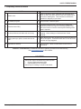
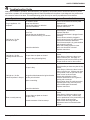
T. Frequently Asked Questions
Odors and vapors released during initial operation.
• Curing of high temperature paint.
• Open windows for air circulation.
Odors may be irritating to sensitive individuals.
CAUTION
CONTACT YOUR DEALER for additional information regarding operation and troubleshooting.
Visit www.quadrare.com to nd a dealer.
ISSUES SOLUTIONS
1 Metallic noise. 1
Noise is caused by metal expanding and contracting as it
heats up and cools down, similar to the sound produced by
a furnace or heating duct. This noise does not affect the
operation or longevity of your insert.
2 Ash buildup on glass. 2 This is normal. Clean the glass.
3 Glass has turned dirty. 3
Excessive build up of ash. The lower burn settings will
produce more ash, the higher burn settings produce less.
The more it burns on low the more frequent cleaning of the
glass is required.
4 Fire has tall ames with black tails and is lazy. 4
The feed rate needs to be reduced or the re pot needs
cleaning. Heat exchanger of exhaust blower needs
cleaning.
5
Smokey start-up or puffs of smoke from the air
wash.
5
Either the re pot is dirty or there is too much fuel at start-up
and not enough air. Close down feed rate 1/4 inch at a time
until this no longer happens.
6 Large ame at start-up. 6
This is normal. Flame will settle down once the re is
established.

18 February 11, 20197021-155H
CASTILE FREESTANDING
3 Maintenance and Service
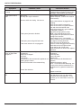
A. Quick Reference Maintenance Chart
NOTICE: These are recommendations. Clean more frequently if you encounter heavy build-up of ash at the
recommended interval or you see soot coming from the vent. Not properly cleaning your appliance
on a regular basis will void your warranty.
Cleaning or Inspection Frequency Daily Weekly
Every 2
Weeks
Monthly Yearly
Ash Pan - Burning Wood Pellets Every 5 bags of fuel OR X
Ash Pan - Burning Alternate
Fuels
Every 1 bag of fuel OR X
Ash Removal from Firebox
More frequently depending
on the fuel type or ash build-
up
OR X
Blower, Combustion (Exhaust)
More frequently depending
on the fuel type
OR X
Blower, Convection
More frequently depending
on the operating environment
OR X
Door Latch Inspection Prior to heating season OR X
Firebox - Prepare for Non-Burn
Season
At end of heating season OR X
Fire pot - Burning Softwood
Pellets
Every 5 bags OR X
Fire pot - Burning Hardwood
Pellets
Every 3 bags OR X
Fire pot - Burning Alternate Fuels Every 1 bag OR X
Glass
When clear view of re pot
becomes obscured
OR X
Heat Exchanger & Drop Tube Every 1 ton of fuel OR X
Hopper
Every 1 ton of fuel or when
changing fuel types
OR X
Venting System
More frequently depending
on the fuel type
OR X
Follow the detailed instructions found in this section for each step listed in the chart below.
When properly maintained, your replace will give
you many years of trouble-free service. Contact your
dealer to answer question regarding proper operation,
troubleshooting and service for your appliance. Visit
www.quadrare.com/owner-resources to view basic
troubleshooting, FAQs, use & care videos. We recommend
annual service by a qualied service technician.
This pellet appliance has a manufacturer-set minimum
low burn rate that must not be altered. It is against federal
regulations to alter this setting or otherwise operate this
pellet appliance in a manner inconsistent with operating
instructions in this manual.
Shock and Smoke Hazard
• Turn down thermostat, let appliance
completely cool and exhaust blower must
be off. Now you can unplug appliance
before servicing.
• Smoke spillage into room can occur if
appliance is not cool before unplugging.
• Risk of shock if appliance not unplugged
before servicing appliance.
CAUTION

19February 11, 2019 7021-155H
CASTILE FREESTANDING
B. General Maintenance and Cleaning
1. Types of Fuel
Depending on the type of fuel you are burning will dictate
how often you have to clean your re pot.
If the fuel you are burning has a high dirt or ash content or
you are burning shelled eld corn, it may be necessary to
clean the re pot more than once a day.
Dirty fuel will cause clinkers to form in the re pot. A clinker
is formed when dirt, ash or a non-burnable substance is
heated to 2000°F (1093°C) and becomes glass-like. See
page 34 in this section for more details on fuels with high
ash content.
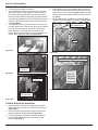
2. Cleaning Fire pot with Cleaning Rod & Fire pot
Scraper
• Frequency: Daily or more often as needed
• By: Homeowner
a. The appliance must be in complete shutdown and cool
and the exhaust blower off. If you are just cleaning the
re pot, there is no need to unplug the appliance.
b. Pull re pot cleaning rod OUT a couple of times to
help shake debris loose. If rod is hard to pull, it may
be necessary to use your re pot clean-out tool to chip
away material that has built up on the bottom plate of
the re pot and to push out any clinkers. Larger clinkers
may have to be removed from the top of the re pot.
Corn clinkers can be especially difcult to break up.
c. The re pot oor plate must be fully closed when
nished (Figure 19.1).
a. There must not be any hot ashes in the rebox during
cleaning so allow the appliance to completely cool. The
rebox ash should be removed every time the exhaust
path is cleaned. Frequent cleaning of the ash in the
rebox will help slow down the build-up of ash in the
exhaust blower and vent system.
b. Plug in your appliance, if unplugged, and turn the
thermostat on and immediately shut it off to start the
exhaust blower on its cycle time. It will pull y ash out
the exhaust instead of into the room.
c. Open cast hinged face. Directly underneath the rebox
door and to the left and right of the re pot are 2
cleaning slide plates with nger holes. Pull both slide
plates out and then open the glass door. Sweep the
remaining ash from the rebox into the 2 open holes. A
paint brush works well for this. Close slide plates.
d. This ash is deposited in the same ash pan as the re
pot debris. The ash pan should be emptied every time
you clean the rebox. Remember to place the ash and
debris into a metal or noncombustible container.
e. The 2 cleaning slide plates must be fully closed when
cleaning is complete. See Disposal of Ashes.
4. Cleaning Ash Pan
• Frequency: Weekly or every 5 bags of fuel
• By: Homeowner
Locate the ash pan underneath the re pot. Open the
bottom ash door and slide the ash pan straight out. Empty
into a non-combustible container and re-install ash pan.
See Disposal of Ashes.
WARNING
Fire Risk
• NEVER pull re pot cleaning rod or cleaning
slide plates out when appliance is operating.
• The cleaning slide plates must be fully
CLOSED when appliance is operating.
• Hot pellets may fall into ash pan and start a
re or mis-starts due to lack of vacuum.
3. Ash Removal from Firebox
• Frequency: Every 5 bags or weekly or more
frequently depending on ash build-up.
• By: Homeowner
WARNING
Fire Risk
• The cleaning slide plates must be fully
CLOSED when appliance is operating. Hot
pellets may fall into ash pan and start a re.
5. Disposal of Ashes
• Frequency: As needed
• By: Homeowner
Ashes should be placed in a steel container with a tight-
tting lid. The container of ashes should be moved outdoors
immediately and placed on a non-combustible oor or
on the ground, well away from all combustible materials,
pending nal disposal.
If the ashes are disposed of by burial in soil or otherwise
locally dispersed, they should be retained in the closed
container until all cinders have thoroughly cooled. Other
waste shall not be placed in this container.
WARNING
Disposal of Ashes
• Ashes should be placed in metal container
with tight tting lid.
• Ashes should be retained in closed
container until all cinders have thoroughly
cooled.
Back side of Firepot
Firepot floor left open
Figure 19.1

20 February 11, 20197021-155H
CASTILE FREESTANDING
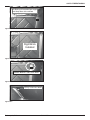
Figure 20.1
Heat Exchanger Tubes
Cleaning Rods
Figure 20.2
Vacuum inside
Exhaust Venting
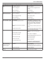
6. Cleaning Heat Exchanger Chambers & Drop Tube
• Frequency: Monthly or every 1 ton of fuel
• By: Homeowner
The amount of ash buildup in the re pot will be a good
guide to determine how often you should clean the heat
exchangers.
a. Allow the appliance to completely cool down before
pulling the cleaning rods. Turn the thermostat on and
then immediately off to start the exhaust blower on its
cycle time. It will pull y ash out the exhaust instead of
into the room.
b. Locate the 2 exposed rods directly underneath the heat
exchanger tubes (Figure 20.1).
c. To clean, pull the rods straight out until it stops,
approximately 8 inches (203mm). Slide the rods OUT
and IN a couple of times.
7. Cleaning Beneath Heat Exchanger
• Frequency: Monthly or after burning 1 ton of fuel
• By: Homeowner
a. Be sure the appliance is allowed to cool, has been
unplugged and the exhaust blower is off.
b. A more thorough cleaning is needed to remove the
excess ash that is left behind from the use of the
cleaning rods for the heat exchanger tubes.
c. The ash will be resting on the back of the bafe. This
will require removing the cast bafe. Please refer to
page 35 for a detailed explanation of removing the
bafe.
WARNING
Heat exchanger cleaning rods may be
warm to the touch. For safety purposes
wear gloves.
Do not pull heat exchanger cleaning rods
while appliance is operating.
Push cleaning rods IN when done, DO
NOT leave cleaning rods OUT. Injury can
occur.
8. Cleaning the Exhaust Path
• Frequency: Every 25 bags or monthly or more
frequently depending on ash build-up.
• By: Homeowner
a. Appliance must be completely cool.
b. Open cast hinge face. Remove bafe and right
brick and thoroughly vacuum the area and continue
throughout the rest of the rebox.
c. Replace right brick and bafe and close cast hinge
face.
9. Cleaning the Hopper
• Frequency: Monthly or after burning 50 bags of fuel or
when changing fuel type
• By: Homeowner
After burning approximately 1 ton of fuel you will need to
clean the hopper to prevent sawdust build-up.
A combination of sawdust and pellets on the auger reduces
the amount of fuel supply to the re pot. This can result in
nuisance shutdowns and mis-starts.
a. The appliance must be in complete shutdown. Allow
the appliance to completely cool down.
b. Empty the hopper of any remaining pellets.
c. Vacuum the hopper and feed tube.
NOTE:
Hearth & Home Technologies recommends to use a
heavy duty vacuum cleaners specically designed
for solid fuel appliance cleaning.
La page est en cours de chargement...
La page est en cours de chargement...
La page est en cours de chargement...
La page est en cours de chargement...
La page est en cours de chargement...
La page est en cours de chargement...
La page est en cours de chargement...
La page est en cours de chargement...
La page est en cours de chargement...
La page est en cours de chargement...
La page est en cours de chargement...
La page est en cours de chargement...
La page est en cours de chargement...
La page est en cours de chargement...
La page est en cours de chargement...
La page est en cours de chargement...
La page est en cours de chargement...
La page est en cours de chargement...
La page est en cours de chargement...
La page est en cours de chargement...
-
 1
1
-
 2
2
-
 3
3
-
 4
4
-
 5
5
-
 6
6
-
 7
7
-
 8
8
-
 9
9
-
 10
10
-
 11
11
-
 12
12
-
 13
13
-
 14
14
-
 15
15
-
 16
16
-
 17
17
-
 18
18
-
 19
19
-
 20
20
-
 21
21
-
 22
22
-
 23
23
-
 24
24
-
 25
25
-
 26
26
-
 27
27
-
 28
28
-
 29
29
-
 30
30
-
 31
31
-
 32
32
-
 33
33
-
 34
34
-
 35
35
-
 36
36
-
 37
37
-
 38
38
-
 39
39
-
 40
40


Quadrafire Castile Pellet Stove Le manuel du propriétaire
- Catégorie
- Poêles
- Taper
- Le manuel du propriétaire
dans d''autres langues
Documents connexes
-
 Quadrafire Castile Pellet Stove Manuel utilisateur
-
 Quadrafire Santa Fe Pellet Stove Le manuel du propriétaire
-
 Quadrafire Castile Pellet Stove Manuel utilisateur
-
 Quadrafire Santa Fe Pellet Stove Manuel utilisateur
-
 Quadrafire Quadra-Fire CB1200M-MBK Le manuel du propriétaire
-
 Quadrafire Castile Pellet Insert Manuel utilisateur
-
 Quadrafire Castile Pellet Insert Manuel utilisateur
-
 Quadrafire Mt. Vernon AE Pellet Stove Manuel utilisateur
-
 Quadrafire Santa Fe Pellet Stove Manuel utilisateur


Autres documents
-
 Greenfire Greenfire GF55 Le manuel du propriétaire
-
Harman Accentra52i-TC Pellet Insert Le manuel du propriétaire
-
Quadra-Fire MTVERNON-AE-PDB Le manuel du propriétaire
-
Lux TX1500E Manuel utilisateur
-
 Castle Pellet Stoves 41278 CASTLE SERENITY 2.0 Le manuel du propriétaire
-
-
CASTLE 12327 Manuel utilisateur
-
-
-
 Hampton Bay Greenfire GC60-2 Le manuel du propriétaire


