Amprobe TMA10A Manuel utilisateur
- Catégorie
- Mesure
- Taper
- Manuel utilisateur

TMA10A
Anemometer
User Manual
ENG FRE
SPA
GER ITA


TMA10A
Anemometer
User Manual
6/2018, 6011186 Rev B
©2018 Amprobe
All rights reserved. Printed in Taiwan
English

Limited Warranty and Limitation of Liability
Your Amprobe product will be free from defects in material and
workmanship for one year from the date of purchase unless local
laws require otherwise. This warranty does not cover fuses, disposable
batteries or damage from accident, neglect, misuse, alteration,
contamination, or abnormal conditions of operation or handling.
Resellers are not authorized to extend any other warranty on the
behalf of Amprobe. To obtain service during the warranty period,
return the product with proof of purchase to an authorized Amprobe
Service Center or to an Amprobe dealer or distributor. See Repair
Section for details. THIS WARRANTY IS YOUR ONLY REMEDY. ALL
OTHER WARRANTIES - WHETHER EXPRESS, IMPLIED OR STATUTORY
- INCLUDING IMPLIED WARRANTIES OF FITNESS FOR A PARTICULAR
PURPOSE OR MERCHANTABILITY, ARE HEREBY DISCLAIMED.
MANUFACTURER SHALL NOT BE LIABLE FOR ANY SPECIAL, INDIRECT,
INCIDENTAL OR CONSEQUENTIAL DAMAGES OR LOSSES, ARISING
FROM ANY CAUSE OR THEORY. Since some states or countries do
not allow the exclusion or limitation of an implied warranty or of
incidental or consequential damages, this limitation of liability may not
apply to you.
Repair
All Amprobe returned for warranty or non-warranty repair or for
calibration should be accompanied by the following: your name,
company’s name, address, telephone number, and proof of purchase.
Additionally, please include a brief description of the problem or the
service requested and include the test leads with the meter. Non-
warranty repair or replacement charges should be remitted in the
form of a check, a money order, credit card with expiration date, or a
purchase order made payable to Amprobe.
In-warranty Repairs and Replacement – All Countries
Please read the warranty statement and check your battery before
requesting repair. During the warranty period, any defective test tool
can be returned to your Amprobe distributor for an exchange for the
same or like product. Please check the “Where to Buy” section on
amprobe.com for a list of distributors near you. Additionally, in the
United States and Canada, in-warranty repair and replacement units
can also be sent to an Amprobe Service Center (see address below).

Non-warranty Repairs and Replacement
– United States and Canada
Non-warranty repairs in the United States and Canada should be sent
to an Amprobe Service Center. Call Amprobe or inquire at your point
of purchase for current repair and replacement rates.
USA: Canada:
Amprobe Amprobe
Everett, WA 98203 Mississauga, ON L4Z 1X9
Tel: 877-AMPROBE (267-7623) Tel: 905-890-7600
Non-warranty Repairs and Replacement – Europe
European non-warranty units can be replaced by your Beha-Amprobe
distributor for a nominal charge. Please check the “Where to Buy”
section on beha-amprobe.com for a list of distributors near you.
Beha-Amprobe
Division and reg. trademark of Fluke Corp. (USA)
Germany* United Kingdom
In den Engematten 14 52 Hurricane Way
79286 Glottertal Norwich, Norfolk
Germany NR6 6JB United Kingdom
Phone: +49 (0) 7684 8009 - 0 Phone: +44 (0) 1603 25 6662
beha-amprobe.de beha-amprobe.com
The Netherlands - Headquarters**
Science Park Eindhoven 5110
5692 EC Son
The Netherlands
Phone: +31 (0) 40 267 51 00
beha-amprobe.com
*(Correspondence only – no repair or replacement available from this
address. European customers please contact your distributor.)
**single contact address in EEA Fluke Europe BV


1
TMA10A Anemometer/Thermometer
Contents
USING THE PUSHBUTTONS ..................................................... 2
DISPLAY INDICATORS .............................................................. 3
MAKING MEASUREMENTS ..................................................... 4
Air Velocity Measurements ................................................ 4
Air Flow Measurements ..................................................... 4
Single Point MIN/MAX/AVG Recording ............................. 5
Multi Point Average Recording .........................................5
Data Hold Feature .............................................................. 6
Changing the Units of Measure ......................................... 6
AUTO POWER OFF .................................................................. 7
ERROR MESSAGE DISPLAY...................................................... 7
USEFUL EQUATIONS AND CONVERSIONS .............................7
Cubic Equations .................................................................. 7
Units Conversion Table .......................................................7
REPLACING THE BATTERY ....................................................... 7
SPECIFICATIONS .......................................................................8

2
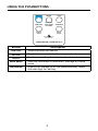
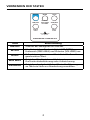
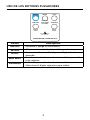
USING THE PUSHBUTTONS
VELOCITY
FREE AREA
VOLUMES
Please See Manual
For Operation
ON /OFF MODEHOLD
MIN MAX
AVERAGE
SINGLE
POINT
MULTI-
POINT
ANEMOMETER THERMOMETER
Button Description
ON/OFF
Turns the meter on and off.
MODE
Toggle between velocity, free area, and volume.
HOLD
Captures a reading. Sets digit to the desired value.
MIN MAX
View the minimum or maximum. Average or record
value.
AVERAGE
Display the average of all the measurements. Select
the next digit for editing.

3
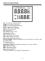
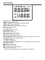
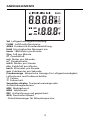
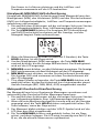
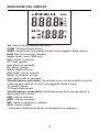
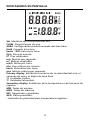
DISPLAY INDICATORS
Vel Air velocity measurement.
FLOW Air flow/air volumen.
AREA Free area default setting.
Hold Freezes the reading.
knots 1850 meters per hour.
ft/m Feet per minute.
ft2 Square feet.
m/s Meters per second.
m2 Square meters.
mil/h Miles per hour.
cfm Cubic feet per minute.
km/h Kilometers per hour.
cms Cubic meters per second.
Primary display Numerical display for air velocity, air volume, and
free area digit.
°C Celsius units.
°F Fahrenheit units.
Secondary display Temperature display or record number.
MIN Minimum data.
MAX Maximum data.
REC Record and saved.
AVG Average data.
- Polarity indicator for negative temperature.

4
MAKING MEASUREMENTS
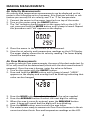
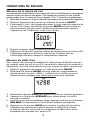
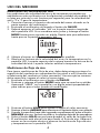
Air Velocity Measurements
Air velocity and temperature measurements can be displayed on this
meter in the following units of measure: ft/m (feet per minute) or m/s
(meters per second) for air velocity and °F or °C for temperature.
1. Connect the sensor to the sensor input jack on top of the meter.
2. Turn on the meter using the ON/OFF button.
3. The 'Vel' indicator should appear on the upper left on the LCD. If
not, press and hold the MODE button until a beep is heard. Repeat
this procedure until 'Vel' appears on the display.
4. Place the sensor in the air current to be measured.
5. View the air velocity and temperature readings on the LCD Display.
The upper display shows the air velocity reading. The lower display
shows the temperature.
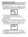
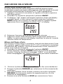
Air Flow Measurements
In order to take air flow measurements, the area of the duct under test (in
ft2 or m2) must first be determined (check with the duct manufacturer if
necessary). Once the area is known, enter the value as follows:
1. Turn on the meter with the ON/OFF button.
2. Press and hold the MODE button until a beep is heard. “AREA”
appears on the display and one digit will be blinking indicating that
value can be changed.
3. Press the HOLD button to adjust the digit to the value needed.
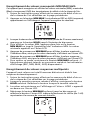
4. Press the AVERAGE button to select the next digit for editing.
5. When the area is correctly entered, press the MIN MAX button
once. A beep will sound and the digits will stop blinking.
6. Press the HOLD button once to store the area value.
7. The meter is now ready to measure air flow. Place the sensor in the air
current and view the air flow and temperature readings on the LCD.

5
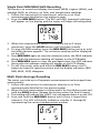
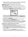
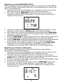
Single Point MIN/MAX/AVG Recording
This meter can record and display the lowest (MIN), highest (MAX), and
average (AVG) air velocity, air flow, and temperature readings.
1. Follow the instructions for starting air velocity or air flow
measurements detailed on the previous page.
2. Press the MIN MAX button. The REC and AVG (average) indicators
will appear on the display and the meter will begin recording data.
3.
When the measurement session is complete (up to 2 hours
maximum), press the HOLD button until the beep sounds.
4. To view the MIN reading, press the MIN MAX button twice or until
the MIN indicator appears. The minimum reading will be displayed
on the LCD.
5. Press MIN MAX again to view the maximum value, the MAX indicator
along with the maximum reading will appear on the LCD display.
6. Press MIN MAX again to view the averaged value, the AVG indicator
along with the average reading will appear on the LCD display.
7. To exit this mode, press and hold the MIN MAX button until 2
beeps are heard in rapid succession and the display indicators (REC,
MIN, MAX, AVG) disappear.
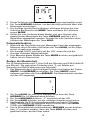
Multi Point Average Recording
The meter can take up to 8 separate measurements and average them
automatically.
1. Follow the instructions for starting air velocity or air flow
measurements detailed on the previous page.
2. When the first measurement is taken and is on the display, press and
hold the HOLD button. Release the button when the tone is heard.
3. The reading will hold and the 'HOLD' icon will appear above it on the LCD.
4. Press and hold the MIN MAX button until a tone is heard then
release it. The LCD will briefly indicate a number (1 through 8)
representing the current measurement number.

6
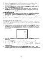
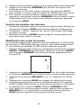
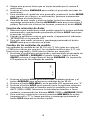
5. Repeat this process until up to 8 measurements have been taken.
6. Press the AVERAGE button to display the average of all the
measurements.
7. To display the average air flow, press the MODE button to enter the
area, then MODE again for air flow.
8. To exit this mode and erase all stored readings, press and hold the
AVERAGE button until 2 beeps are heard. To exit without erasing
readings, press the HOLD button.
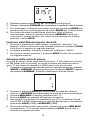
Data Hold Feature
1. While taking measurements you can freeze the displayed reading by
pressing and holding the HOLD button until a beep is heard.
2. The 'HOLD' indicator will appear on the LCD when the display is in this
mode.
3. Press and hold the HOLD button until a beep is heard to exit this mode.
Changing the Units of Measure
U.S. units of measure are °F, ft/m (feet per minute), and CFM (cubic feet
per minute). Metric units are: °C, m/s (meters per second), and CMS (cubic
meters per second).
1. Turn the meter on by pressing and holding both the ON/OFF and the
AVERAGE buttons simultaneously. Release the ON/OFF button first
then release the AVERAGE button. The units of measure will appear
on the LCD.
2. Press the HOLD button to select Metric and the AVERAGE button to
select U.S.
3. Press the MIN MAX button and an "S" will appear on the LCD.
4. Press the HOLD button to advance to the next selection.
5. The baud rate for PC Interface models will appear (1200 or 2400). Select
the baud rate, if necessary, by pressing the HOLD (1200) or AVERAGE
(2400) button.
6. To return to normal operation, press MIN MAX again (the "S" will
reappear) then press and hold the HOLD button until the beep is heard.

7
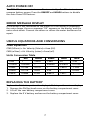
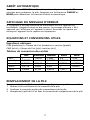
AUTO POWER OFF
The TMA10A Anemometer turns off automatically after 20 minutes to
conserve battery power. Press the ON/OFF and HOLD buttons to disable
the Auto Power Off feature.
ERROR MESSAGE DISPLAY
If the sensor is not connected to the meter or if the sensor is inoperable,
the meter beeps, the error message "E6" appears on the display, and the
meter shuts down. Connect the sensor or return the meter and sensor for
repair.
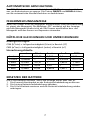
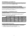
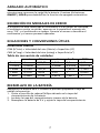
USEFUL EQUATIONS AND CONVERSIONS
Cubic Equations
CFM (ft3/min) = Air Velocity (ft/min) x Area (ft2)
CMS (m3/sec) = Air Velocity (m/sec) x Area (m2)
Units Conversion Table
m/s ft/min knots km/h MPH
1 m/s 1 196.87 1.944 3.6 2.24
1 ft/min 0.00508 1 0.00987 0.01829 0.01138
1 knot 0.5144 101.27 1 1.8519 1.1523
1 km/h 0.2778 54.69 0.54 1 0.6222
1 MPH 0.4464 87.89 0.8679 1.6071 1
REPLACING THE BATTERY
Replace the 9 V battery when the display is flashing or there is no display.
1. Remove the Phillips head screw on the battery compartment cover.
2. Lift off the rear battery compartment cover.
3. Replace the 9 V battery and secure the battery compartment cover.

8
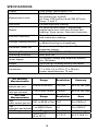
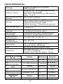
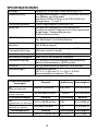
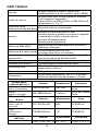
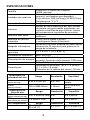
SPECIFICATIONS
Display Dual 4-digit (9999 count) LCD
Measurement units
Air Velocity: ft/min (feet per minute);
m/s (meters per second)
Air Flow: CMS (m3/sec) and CFM (ft
3
/min);
Temp: °C and °F
Data hold Freezes displayed reading
Sensors
Air velocity/flow sensor: Conventional
angled vane arms with low-friction ball
bearing. Temp. sensor: Precision thermistor
MIN MAX Memory
Record and view minimum
and maximum readings
Average reading memory
Single Point (up to 2 hours)
or Multi-Point (up to 8 readings)
Automatic Power off
Sleep mode (with bypass) after 20 mins.
conserves energy
Operating Temperature 32 °F to 122 °F (0°C to 50 °C)
Operating Humidity Max. 80% RH
Power Supply
9 V battery (Heavy duty alkaline); Battery
life: 100 hours
Weight 0.8 lb (363 g) including battery and sensor
Dimensions
Main instrument:
7.1 x 2.8 x 1.4 in (181 x 71 x 38 mm)
Sensor head diameter: 70 mm
Air Velocity
Measurements
Range Resolution Accuracy
m/s
(meters per sec)
0.40 to 25.00 m/s 0.01 m/s ±2% of full scale
ft/min
(feet per minute)
125 to 4900 ft/min 1 ft/min ±2% of full scale
Air Flow
Measurements
Range Resolution Area
CMS
(cubic meters per sec.)
0.01 to 99.99 m
3
/sec 0.01 0 to 9.999 m
2
CFM
(cubic feet per minute)
1 to 9999 ft3/min 1.0 0 to 9.999 ft
2
Air Temperature Range Resolution Accuracy
32 to 122 °F
(0 to 50 °C)
0.1 °F/°C ±1.5 °F (0.8 °C)

TMA10A
Anémomètre
Mode d’emploi
6/2018, 6011186 Rev B
©2018 Amprobe
Tous droits réservés. Imprimé à Taïwan
Français

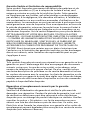
Garantie limitée et limitation de responsabilité
Votre produit Amprobe sera exempt de défauts de matériaux et de
fabrication pendant un (1) an à compter de la date d’achat, sauf
exigence contraire en vertu de la juridiction locale. Cette garantie
ne s’applique pas aux fusibles, aux piles jetables ou endommagées
par accident, à la négligence, à la mauvaise utilisation, à l’altération,
à la contamination ou aux conditions anormales d’utilisation ou de
manipulation. Les revendeurs ne sont pas autorisés à prolonger toute
autre garantie au nom de Amprobe. Pour une réparation au cours de
la période de garantie, retournez le produit avec la preuve d’achat à
un centre de service autorisé par Amprobe ou à un revendeur ou un
distributeur Amprobe. Voir la section Réparation pour plus de détails.
CETTE GARANTIE EST VOTRE SEUL RECOURS. TOUTES LES AUTRES
GARANTIES – QU’ELLES SOIENT EXPLICITES, IMPLICITES OU JURIDIQUES
– Y COMPRIS LES GARANTIES IMPLICITES D’ADAPTATION À UN USAGE
PARTICULIER OU MARCHAND, SONT EXCLUES. LE FABRICANT NE
SERA PAS RESPONSABLE DES DOMMAGES SPECIAUX, INDIRECTS,
ACCESSOIRES OU CONSECUTIFS PROVENANT DE TOUTE CAUSE OU
THEORIE. Etant donné que certains pays ou états n’autorisent pas
l’exclusion ou la limitation des garanties implicites ou des dommages
directs ou indirects, cette limitation de responsabilité peut ne pas
s’appliquer à vous.
Réparation
Tout produit Amprobe retourné pour réparation sous garantie ou hors
garantie ou pour l’étalonnage doit être accompagné des documents
suivants:votre nom, le nom de votre société, votre adresse, votre
numéro de téléphone et la preuve d’achat. De plus, veuillez inclure
une brève description du problème ou du service demandé et incluez
les cordons de mesure avec le compteur. Les frais de réparation ou de
remplacement non garantis doivent être réglés sous forme de chèque,
mandat, carte de crédit avec date d’expiration ou bon de commande
payable à Amprobe/Beha-Amprobe
Réparation et remplacement couverts par la garantie
– Tous les pays
Veuillez lire la déclaration de garantie et vérifier la pile avant de
demander une réparation. Pendant la période de garantie, tout outil
de vérification défectueux peut être retourné à votre distributeur
Amprobe pour un échange de produit identique ou similaire. Veuillez
consulter la section «Où acheter» sur le site amprobe.com pour
obtenir une liste des distributeurs près de chez vous. En outre, aux
États-Unis et au Canada, les réparations sous garantie et les unités de
remplacement peuvent également être envoyés à un centre de service
Amprobe (voir adresse ci-dessous).

Réparation et remplacement non couverts par la garantie
– États-Unis et Canada
Pour les réparations non couvertes par la garantie aux États-Unis et au
Canada, l’appareil doit être envoyé à un centre de service Amprobe.
Appelez Amprobe ou renseignez-vous auprès de votre point de vente
pour les tarifs de réparation et de remplacement actuels.
États-Unis: Canada:
Amprobe Amprobe
Everett, WA 98203 Mississauga ON L4Z 1X9
Tél.: 877-AMPROBE (267-7623) Tél.: 905-890-7600
Réparation et remplacement non couverts par la garantie
– Europe
Les unités hors garantie européenne peuvent être remplacées par
votre distributeur Amprobe/Beha-Amprobe pour une somme modique.
Veuillez consulter la section «Où acheter» sur le site beha-amprobe.
com pour obtenir une liste des distributeurs près de chez vous.
Beha-Amprobe
Division et marque déposée de Fluke Corp. (USA)
Allemagne* Royaume-Uni
In den Engematten 14 52 Hurricane Way
79286 Glottertal Norwich, Norfolk
Allemagne NR6 6JB Royaume-Uni
Tél. : +49 (0) 7684 8009 - 0 Tél. : +44 (0) 1603 25 6662
beha-amprobe.de beha-amprobe.com
Pays-Bas - Siège social**
Science Park Eindhoven 5110
5692 EC Son
Pays-Bas
Tél. : +31 (0) 40 267 51 00
beha-amprobe.com
*(Correspondance uniquement: aucune réparation ou remplacement
à cette adresse.
Clients européens, veuillez contacter votre distributeur.)
**adresse de contact unique dans l’EEE Fluke Europe BV


1
Thermomètre/anémomètre TMA10A
Table des matières
UTILISATION DES BOUTONS POUSSOIRS .............................. 2
INDICATEURS ........................................................................... 3
OPÉRATIONS DE MESURE ....................................................... 4
Mesures de la vitesse de l’air ............................................. 4
Mesures du débit d’air ....................................................... 4
Enregistrement de valeurs monopoints MIN/MAX/AVG .. 5
Enregistrement de valeurs moyennes multipoints ........... 5
Fonction de maintien des données ................................... 6
Modification des unités de mesure ................................... 6
ARRÊT AUTOMATIQUE ........................................................... 7
AFFICHAGE DU MESSAGE D’ERREUR ..................................... 7
EQUATIONS ET CONVERSIONS UTILES .................................. 7
Equations cubiques............................................................. 7
Tableau de conversion des unités ...................................... 7
REMPLACEMENT DE LA PILE ................................................... 7
CARACTÉRISTIQUES ................................................................ 8

2
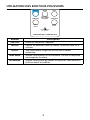
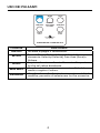
UTILISATION DES BOUTONS POUSSOIRS
VELOCITY
FREE AREA
VOLUMES
Please See Manual
For Operation
ON /OFF MODEHOLD
MIN MAX
AVERAGE
SINGLE
POINT
MULTI-
POINT
ANEMOMETER THERMOMETER
Bouton Description
ON/OFF
Active ou désactive l’appareil.
MODE
Permet de basculer entre la vitesse, la section libre et le
volume.
HOLD
Saisit une valeur. Règle les chiffres sur la valeur
souhaitée.
MIN MAX
Affiche le minimum ou le maximum. Affiche la moyenne
ou enregistre la valeur.
AVERAGE
Affiche la moyenne de toutes les mesures. Sélectionne le
chiffre suivant à modifier.
La page charge ...
La page charge ...
La page charge ...
La page charge ...
La page charge ...
La page charge ...
La page charge ...
La page charge ...
La page charge ...
La page charge ...
La page charge ...
La page charge ...
La page charge ...
La page charge ...
La page charge ...
La page charge ...
La page charge ...
La page charge ...
La page charge ...
La page charge ...
La page charge ...
La page charge ...
La page charge ...
La page charge ...
La page charge ...
La page charge ...
La page charge ...
La page charge ...
La page charge ...
La page charge ...
La page charge ...
La page charge ...
La page charge ...
La page charge ...
La page charge ...
La page charge ...
La page charge ...
La page charge ...
La page charge ...
La page charge ...
La page charge ...
La page charge ...
La page charge ...
La page charge ...
-
 1
1
-
 2
2
-
 3
3
-
 4
4
-
 5
5
-
 6
6
-
 7
7
-
 8
8
-
 9
9
-
 10
10
-
 11
11
-
 12
12
-
 13
13
-
 14
14
-
 15
15
-
 16
16
-
 17
17
-
 18
18
-
 19
19
-
 20
20
-
 21
21
-
 22
22
-
 23
23
-
 24
24
-
 25
25
-
 26
26
-
 27
27
-
 28
28
-
 29
29
-
 30
30
-
 31
31
-
 32
32
-
 33
33
-
 34
34
-
 35
35
-
 36
36
-
 37
37
-
 38
38
-
 39
39
-
 40
40
-
 41
41
-
 42
42
-
 43
43
-
 44
44
-
 45
45
-
 46
46
-
 47
47
-
 48
48
-
 49
49
-
 50
50
-
 51
51
-
 52
52
-
 53
53
-
 54
54
-
 55
55
-
 56
56
-
 57
57
-
 58
58
-
 59
59
-
 60
60
-
 61
61
-
 62
62
-
 63
63
-
 64
64


Amprobe TMA10A Manuel utilisateur
- Catégorie
- Mesure
- Taper
- Manuel utilisateur
dans d''autres langues
- italiano: Amprobe TMA10A Manuale utente
- español: Amprobe TMA10A Manual de usuario
- Deutsch: Amprobe TMA10A Benutzerhandbuch
Documents connexes
-
Amprobe AC50A Leakage Clamp Meter Manuel utilisateur
-
-
-
-
-
-
-
Amprobe ACDC-400 Manuel utilisateur
-
Amprobe TMD-10 Manuel utilisateur
-
Amprobe ALC-110 Leakage Clamp Manuel utilisateur
